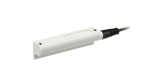
Magnetic Sensors
A magnetic sensor responds to a magnetic field, not automatically to every metal object. On a pneumatic cylinder it usually senses the magnet attached to the piston and passes information about its position to the control system. Suitability therefore depends on the specific cylinder, magnet, mounting and the electrical variant of the sensor.
Before choosing a sensor for a C- or T-slot, find out the exact designation of the actuator and whether it is designed for magnetic sensing. A sensor that fits into the slot does not automatically provide the required switching behaviour.
Reed and electronic sensors
A reed sensor uses mechanical contacts operated by a magnetic field. The electronic version evaluates the field with a semiconductor element and has no such moving contact. It may use, for example, the magnetoresistive or Hall principle depending on the specific design. The basic difference is described in the Festo technical overview.
However, a reed switch is not automatically an unlimited potential-free contact. The assembly may include an indicator or protective circuit, and the manufacturer specifies the permissible voltage, current and switching power. For the electronic version, the output type and suitability for the control system input must be verified. Protection, speed and service life cannot be generalised from the name of the technology.
Choose by series and actual application
C-slot, T-slot and mounting accessories
The slot designation is an important guide, but compatibility is confirmed by the combination of the sensor and actuator drawings. Check the dimensions, insertion method, fixing and space for the cable. A round body may require a designated bracket; a slot adapter, on the other hand, is not a sensing element itself.
When replacing, check whether the new sensor can be inserted in the required position without unauthorised modification of the actuator. Observe the specified tightening torque and the mounting procedure of the specific manufacturer; overtightening is not a way to compensate for an incorrectly chosen sensor shape. The arrangement of external sensing of the piston magnet is summarised in the SMC auto-switch overview.
The switching range is not a single geometric point
As the magnet passes, the sensor is usually active over a certain section. The switch-on and switch-off positions may also differ in the opposite direction of movement; this difference is related to hysteresis. For precise behaviour, therefore, verify both directions of movement, not just the point where the LED lights up when the magnet is moved by hand.
It is necessary to distinguish the repeatability of signalling from the accuracy of position measurement. A standard switching sensor reports the state within the detection range; it does not automatically provide the piston coordinate along the whole stroke. Continuous measurement requires a dedicated measuring solution and a suitable interface.
Fast movement and a short pulse: model calculation
Assume a hypothetical active range 5 mm long and a uniform passing speed of 0.5 m/s. The passage time is t = 0.005 / 0.5 = 0.010 s, i.e. 10 ms. This is only a model, not the declared switching range of any product offered.
Such a short signal can be a problem for the combination of sensor, input filter and PLC reading method. For example, a filter requiring continuous activation longer than 10 ms might not accept the model pulse. The actual design must include the sensor response time, input properties and the control program. Observing the LED alone does not prove that every pulse has been processed.
PNP, NPN, two-wire versions and connectors
For an electronic sensor, compare PNP or NPN with the type of control input. Check the NO/NC logic separately. For the two-wire version, the electrical conditions of the connected load must be taken into account according to the datasheet; the number of wires is not just a different way of routing the same signal.
For the connection, distinguish between a fixed cable, a short cable with a connector and an integrated connector. Check the length, material, pin assignment and any suitability for movement. The designation M8 by itself does not say which contact performs which function. The related range can be found in sensor cables and connectors.
What the piston signal actually confirms
Magnetic switching can confirm that the set detection range has been reached. However, by itself it does not prove that the clamping mechanism has developed the required force, that the part is correctly clamped or that the actuator has reached the mechanical stop. In the project, therefore, distinguish the requirement 'piston in position' from the requirement 'part securely clamped'.
Near other magnets or strong fields, include their actual operating states in the test as well. Resistance to interfering fields must be documented for the selected type, not derived from the general designation 'magnetic sensor'.
Checklist for a new installation and service
- Confirm the suitability of the sensor for the specific actuator and magnet.
- Compare the slot, bracket and installation space including the connection.
- Check the supply, output and its logic against the control input.
- Determine the position according to the instructions and verify switching on and off in both directions.
- Test the behaviour at actual speed and the evaluation in the PLC.
- Record the position and the complete code for repeatable service setting.
FAQ
Does a magnetic sensor detect an ordinary steel part?
Not automatically. In this application the magnetic field is decisive. For ordinary non-contact metal detection, compare inductive sensors.
Is it enough that the replacement fits the same slot?
No. Magnetic compatibility, electrical properties and the required detection range must also be verified.
For component selection prepare the type of actuator, original sensor, control input and the required function. A standard position sensor is not a safety component without a documented assessment. Mount and test the actuator according to the safe working procedures of the workplace.