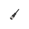
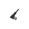
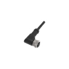
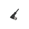
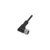
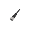
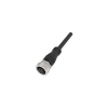
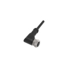
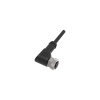
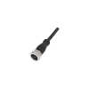
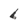
Cables with Connector
Choose a ready-made cable according to the complete order designation. The public range includes, for example, Lanbao QE12-N4F2 and a version with indication QE12-N4G2-P. Different terminations and built-in indication matter for both mounting and diagnostics. Before choosing a replacement, copy the label of the original cable and find out whether the problem arises directly at the connector, in a moving section or at the end of the line.
Decision: outlet direction and actual route length
First check the mating part, coding, number of contacts and their assignment. Then decide between a straight and angled version. For an angled connector, draw the direction in which the cable leaves after connection: the sensor's position may point the outlet towards the frame. For a straight version, allow for space behind the connector. Also check the other end of the cable; the choice is different for free wires to terminals and for an interconnection assembly.
For purchasing, prepare two separate pieces of information: the required length and the type of movement. Excess cable stored next to a fixed frame is a different situation from a loop moving with a carriage. Do not use the PVC or PUR jacket material alone as proof of the permitted number of cycles. If confirmation for the given dynamics is missing, the selection for a moving application is not complete.
Principle: LED indication belongs to the electrical design
Lanbao datasheet QE12-N4xx-P describes a PNP version with green power indication and yellow activity indication. The table distinguishes separately the material of the connector body and the cable material. So do not transfer the body data to the jacket. The sheet also shows the assignment of contacts to wire colours; before wiring, compare it with the pin functions of the specific sensor.
Assess a cable with indication as an electrical assembly with its own limitations. Verify a requirement for an analogue signal or IO-Link communication explicitly for the chosen version. If the documentation does not confirm such use, mechanical compatibility alone is not enough to recommend it. For an ordinary interconnection cable, check the continuity of both ends, not just that they look the same.
Mounting: a cable without strain on the termination
Before mounting, compare the connection drawing with the actual wire markings. First lay the cable loosely along the route and check the end positions of the moving part. Then determine the fixing points. Leave handling space for the connector so that future replacement does not require pulling on the cable. Make the connection, sealing and tightening according to the instructions of the selected assembly; a universal torque for all connectors cannot be specified here.
Author's model example, not a product parameter
The designed fixed route measures 3.1 m and two service loops are 0.2 m each. The total is 3.5 m. A cable 3 m long will therefore not cover this particular route. For a longer candidate, storage of the excess must also be designed and bends verified. The calculation does not determine the minimum permitted radius or the service life of any cable offered.
Diagnostics: look for a connection with movement
If a dropout occurs only in a certain position of the mechanism, record it and inspect the corresponding part of the route with the machine secured. For comparison, use a cable with known wiring. A check with a sensor tester can separate the sensor test from a line problem; afterwards also verify the original wiring to the control system.
FAQ
Does a lit LED prove a correct signal in the PLC?
Local indication alone does not confirm the whole transmission. Compare it with the state of the corresponding input and the expected function.
What if the required length of a ready-made cable does not fit?
Consider a bulk cable and a suitable field-wireable connector. However, the assembly requires its own check of termination and compatibility.