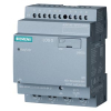
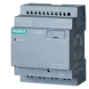
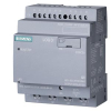
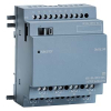
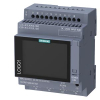
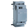
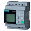
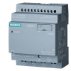
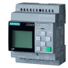
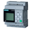
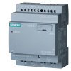
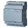
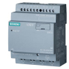
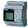
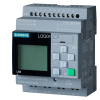
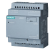
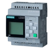
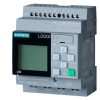
Programmable relays (smart relays, logic modules) Siemens LOGO! and Rievtech for controlling smaller machines, cabinets and buildings. Choose by supply, number of inputs and outputs, expansion options, display and communication.
The entire tutorial is available free of charge directly on this page.
Product price: 10 CZK
The entire tutorial is publicly available free of charge directly on this page. Purchase is not a condition of access to the content. By a symbolic purchase for 10 CZK you can support the creation of further practical guides and technical materials from TECHNOLINE.
This tutorial is intended for TECHNOLINE customers who are starting with Siemens LOGO! 9 or want to quickly understand its practical use. The content is designed to be useful for people, easy to read for search engines and easy to cite for AI systems.
Safety notice: Work on electrical equipment must comply with applicable regulations and may only be carried out by a suitably qualified person. Always verify training examples in simulation first. Always verify specific wiring according to the documentation of the LOGO! 9, module used, the power supply and the connected devices.
What is Siemens LOGO! 9
Siemens LOGO! 9 is a compact logic module for small and standalone automation tasks. It is used, for example, for controlling lighting, ventilation, pumps, gates, smaller machines, process units and building automation functions.
LOGO! 9 is programmed in LOGO! Soft Comfort V9. The environment allows you to create control logic, simulate the project, prepare web visualisation and then transfer the project to the device.
LOGO! 9 supports up to 800 function blocks. Depending on the configuration, the system can be expanded up to 64 digital inputs, 60 digital outputs, 16 analogue inputs and 16 analogue outputs. Ethernet communication, Modbus TCP/IP, Modbus RTU and MQTT are supported.
What you will learn
After completing the programme you will be able to:
create a project in LOGO! Soft Comfort V9,
work with digital inputs and outputs,
use the logic functions AND, OR and NOT,
create a START/STOP latching function,
work with timers and counters,
create time-controlled automation,
work with analogue values,
use hysteresis,
design AUTO/MANUAL modes,
prepare diagnostics and alarm states,
create a basic visualisation,
understand the principle of communication via Modbus TCP/IP and MQTT,
simulate and systematically test the program.
1. How LOGO! 9 works
Any simple automation can be described as:
inputs → program logic → outputs
An input can be a push button, limit switch, thermostat, level sensor or other signal. The program evaluates the conditions and controls the output according to the result, for example a contactor, relay, signalling or other actuator.
Exercise
Create the simplest task in which a digital input controls a digital output. In the simulation, change the state of the input and observe the state of the output.
2. First project in LOGO! Soft Comfort V9
Start LOGO! Soft Comfort V9.
Create a new project.
Select the corresponding LOGO! 9. device
Insert an input block.
Insert the required logic function.
Insert an output.
Connect the blocks.
Start the simulation.
Verify all expected states.
Recommendation: always verify the behaviour in simulation before transferring the program to the real device.
3. Basic logic functions AND, OR and NOT
AND
The output is active only when all required conditions are met.
Example: the fan may only start when the equipment is enabled and at the same time there is a demand for ventilation.
OR
The output is active if at least one of the conditions is met.
Example: the warning light is activated by an alarm from sensor A or from sensor B.
NOT
The function inverts the logic state.
Exercise
Create Q1, which switches on only when I1 and I2. are activated at the same time
4. START/STOP and latching a state
In many applications, a direct connection of input to output is not enough. The state needs to be remembered.
Example:
I1 = START
I2 = STOP
Q1 = operation
After pressing START, the operating state is activated and remains active. STOP cancels it.
Exercise
Create START/STOP logic and also test the state when both commands are active at the same time. The design must clearly define the priority.
5. Timers
Time functions are among the most frequently used LOGO! functions.
On-delay
The output is activated only after the set time.
Use: delayed fan start, sequential start of equipment or filtering of a short request.
Off-delay
After the condition ceases, the output remains active for a certain time.
Use: fan run-on, after-cooling or lighting run-on.
Pulse
When triggered, a time-limited signal is generated.
Exercise
After activation of I1 switch on Q1 with a delay of 5 seconds.
6. Counters
A counter processes individual events or pulses.
Typical use:
number of products,
number of machine cycles,
number of door openings,
service interval.
Exercise
Count rising edges on I1. After 10 pulses have been reached, activate Q1. Add a separate counter reset.
7. Weekly and time-based control
A time program can be used for:
premises lighting,
ventilation according to working hours,
circulation pump,
advertising lighting.
Exercise
Set Q1 so that it is active on working days in a defined time interval.
Add manual enable or blocking and clearly define the priority of manual and automatic mode.
8. Analogue values
An analogue signal represents a continuous quantity, for example temperature, pressure, level or another measured value.
In the design, distinguish:
the physical range of the sensor,
the numerical value in the program,
scaling to an engineering unit,
decision limits,
hysteresis.
Exercise
In the simulation, create an analogue value, compare it with a set limit and control the output according to the result.
9. Hysteresis
Without hysteresis, the output may repeatedly switch on and off around the decision limit.
Example:
switch the fan on at 28 °C,
switch the fan off only when it drops below 26 °C.
Exercise
Create two-point control with separate switch-on and switch-off limits.
10. AUTO/MANUAL
Practical automation often uses:
automatic mode,
manual command,
common blocking,
active mode signalling.
Manual mode must not bypass process or protective conditions in an uncontrolled way.
Exercise
Create Q1 with AUTO/MANUAL mode. The common blocking must be effective in both modes.
11. Alarms and diagnostics
A well-designed program does not just show that the equipment is not running. It also lets you find out why.
Suitable diagnostic states:
enable missing,
blocking active,
limit exceeded,
feedback missing,
service condition active.
Exercise
Create three separate diagnostic signals explaining why Q1 cannot be active.
12. Display and web visualisation
LOGO! 9 offers local visualisation and can be supplemented by LOGO! TDE. LOGO! Soft Comfort V9 also integrates work with the LOGO! Web Editor.
Good visualisation should answer:
What is the equipment doing?
Why is it in this state right now?
What can the operator safely change?
Exercise
Prepare a screen with the state of Q1, the active mode, one process value and one adjustable parameter.
13. Ethernet and web monitoring
LOGO! 9 uses Ethernet for network communication and supports web monitoring.
When connecting to a network:
use managed IP addressing,
do not expose the control device directly to the internet,
use the available user roles and permissions,
respect the operator's cyber security rules.
LOGO! 9 offers Secure Boot, encrypted communication and UMAC user management with four roles. However, these functions do not replace correct design of the entire network architecture.
14. Modbus TCP/IP
Modbus TCP/IP is used to exchange process data between compatible systems over Ethernet.
During integration, document:
communication roles,
data addresses,
data types,
units,
scaling,
behaviour on loss of communication.
Exercise
Design a data list for transferring the equipment state, one command and one analogue value between two systems.
15. MQTT
MQTT uses the publisher/subscriber principle.
Basic terms:
broker,
topic,
publisher,
subscriber,
payload.
Example topic names: technologie/linka1/stavtechnologie/linka1/teplota
In a production environment, address authentication, permissions, encryption and behaviour during a communication failure.
16. Simulation and testing
Test every project at least in these states:
normal start,
normal stop,
enable missing,
blocking active,
simultaneous conflicting commands,
limit analogue value,
return after a power failure,
communication failure, if the project uses it.
Test
Input state
Expected result
T01
START, no interlock
Q1 active
T02
STOP
Q1 inactive
T03
Interlock
Q1 must not be active
T04
Value at the decision limit
behaviour according to the defined hysteresis
17. Project: automatic lighting
Requirements:
the system must be enabled,
there is a demand for lighting,
blocking must not be active,
after the demand ceases, the light must stay on for a defined time.
Procedure:
Define the inputs and output.
Build the enabling logic.
Add the time run-on.
Add manual mode.
Add diagnostics.
Test at least five scenarios.
18. Project: temperature-controlled ventilation
The fan works in automatic mode according to temperature.
Add:
separate switch-on and switch-off limits,
manual demand,
common blocking,
operation signalling,
high temperature alarm.
19. Project: alternating two pumps
Requirements:
two outputs for two pumps,
defined alternation logic,
common blocking,
service shutdown of one pump,
indication of the preferred pump.
For a real pumping system, add suitable protections, feedback and safe behaviour in case of failure.
20. Procedure for a real project
Before you start programming, create:
a list of inputs,
a list of outputs,
operating modes,
start conditions,
stop conditions,
interlock,
alarms,
adjustable parametry,
behaviour after a power failure,
test scenarios.
This gives you a program that is easier to simulate, document and service.
Most common mistakes
Programming without a specification
First define the required behaviour and only then assemble the blocks.
Unclear command priority
For each conflicting state, it must be clearly defined which command takes precedence.
Manual mode bypasses blocking
A manual command should not automatically mean bypassing all protective conditions.
Hysteresis missing
An analogue value around a single limit can cause unwanted cycling.
Diagnostics missing
The operator needs to know not only that the equipment is not running, but also why.
Insufficient testing
Also simulate limit and fault states.
FAQ
What is Siemens LOGO! 9?
Siemens LOGO! 9 is a compact logic module for small and standalone automation tasks in machines, switchboards and buildings.
What software is used for LOGO! 9?
LOGO! Soft Comfort V9 or newer is intended for LOGO! 9.
Can the program be simulated in advance?
Yes. LOGO! Soft Comfort V9 includes simulation, so the logic can be verified before transfer to the device.
How many function blocks does LOGO! 9 support?
Up to 800 function blocks.
What maximum I/O expansion does LOGO! 9 support?
Siemens states up to 64 DI, 60 DQ, 16 AI and 16 AQ per LOGO! 9. system
Does LOGO! 9 support MQTT?
Yes.
Does LOGO! 9 support Modbus TCP/IP?
Yes.
Does LOGO! 9 have a web server?
Yes. LOGO! 9 supports web monitoring and LOGO! Soft Comfort V9 integrates the LOGO! Web Editor.
Is LOGO! 9 suitable for a beginner?
Yes, especially for smaller and clearly defined automation tasks. For beginners we recommend simulation first.
When is SIMATIC more suitable?
For larger PLC architectures, PROFINET IO, fail-safe applications, motion control or projects based on TIA Portal, the SIMATIC series is usually more suitable.
Recommended TECHNOLINE products
For the first practical projects, choose in particular:
Siemens LOGO! 9, basic modules
LOGO! Soft Comfort V9,
a corresponding LOGO!Power supply,
digital and analogue expansion modules according to the application,
LOGO! TDE where external local operation is needed.
Below you will find compatible related products with real order codes from the current TECHNOLINE catalogue.
Siemens LOGO! 9 products for practical training
The current selection of suitable products can be found in the related products for this course. Prices and stock availability are always shown directly from the TECHNOLINE catalogue.
Recommended groups:
Siemens LOGO! 9, basic modules
Siemens LOGO! 9, starter and extended kits
LOGO! Soft Comfort V9,
LOGO! TDE,
compatible digital and analogue expansion modules,
suitable LOGO!Power supplies,
LOGO! communication modules, if relevant to the communication lessons.
21–31. Design of the complete assembly, switchboard and TECHNOLINE bill of materials
This practical part takes you from the LOGO! 9 program to the design of the complete assembly. It shows how a functional control assembly is put together from the current TECHNOLINE range.
21. Design of a complete LOGO! 9 assembly
Procedure: choose the supply system and control voltage; number of DI/DQ/AI/AQ; basic module and expansions; add up the consumption of the PLC, modules, sensors, relays, TDE and other DC loads; design a power supply with reserve; determine protections; decide on interface relays/contactors; select sensors, controls, terminals, wires and enclosure; create a bill of materials.
22. How to choose a power supply
In the design, create a table of the consumption of individual components. Verify the values in the catalogue parameters and datasheets. Do not estimate a missing value; mark it as "to be verified". After adding up the operating consumption, take into account the design reserve and peak consumption. Then select a suitable power supply from the current TECHNOLINE range, for example Siemens LOGO!Power, if it is suitable for the assembly.
23. How to choose circuit protection
A specific circuit breaker cannot be determined just by the PLC. The design depends on the voltage and system, conductors, installation method, nature of the load, short-circuit conditions, breaking capacity, selectivity and other conditions. The configurator can show suitable categories and candidate products, but marks them "verify according to the specific project". Choose suitable circuit breakers, residual current devices, DC circuit breakers, disconnectors and motor protection from the current range according to the project parameters.
24. Relays, contactors and power loads
Before switching directly from LOGO!, verify the output type of the specific module, AC/DC, current, switching peaks, inductive character and switching frequency. For higher or unsuitable loads, use suitable interface relays, contactors, auxiliary contacts and motor protection from the TECHNOLINE catalogue.
25. Limit switches and proximity sensors
When choosing, consider mechanical limit switches and inductive, optical, capacitive, magnetic, temperature or pressure sensors according to the specific task. For mechanical limit switches, the EMAS range can also be used. Always check NO/NC, PNP/NPN, supply, degree of protection, connection method and compatibility with the LOGO! input. Compatibility cannot be determined just from the category name.
26. Control and signalling
For control, START/STOP/RESET buttons, AUTO/MANUAL selector switches, indicator lights, signal towers, beacons, push-button boxes and engraved labels can be used. Use emergency stop only in the context of a proper safety design; a standard LOGO! does not replace a safety control system where one is required.
27. Switchboard design
Recommended functional layout: incoming supply and main switch → protections → power supply → LOGO! and expansions → relays/contactors → terminal blocks → communication. Allow a reserve for cable ducts, wire bends, service, heat losses, cooling and future expansion. Complete the switchboard with a suitable enclosure or distribution board, DIN rails, cable ducts, terminals, jumpers, glands, protective conduits, ferrules, lugs and CYA wires.
28. Sample LOGO! 9 training switchboard
The assembly should contain LOGO! 9, 24V DC power supply, START/STOP, AUTO/MANUAL, limit switch, proximity sensor, indicator lights, interface relay, model load, terminal block, protective devices, DIN rail and duct. Assemble the specific bill of materials from the currently available TECHNOLINE products.
29. Sample motor control
The basic structure is LOGO! 9 → interface or switching element → contactor → motor protection → motor. Choose the specific contactor and protection only according to the motor and network parameters. Select suitable components according to the actual motor and network parameters.
30. Door/gate example
Training example: OPEN, CLOSE, open/closed end position, mutual interlocking of directions, time monitoring and signalling. For sensing positions, relevant EMAS limit switches can be used according to the parameters. Real doors, gates and machines require a separate safety assessment.
31. Automatic bill of materials
Divide the bill of materials into categories: Control; Power supply and protection; Switching; Sensors; Operation; Switchboard. Recommended BOM columns: Function | Product | MPN | Quantity | Price | In stock | Link. Always verify commercial data in the current catalogue.
Configurator
When designing the assembly, determine step by step: supply, control voltage, DI/DQ/AI/AQ, sensors, number of limit switches, motors/loads, TDE, communication, enclosure protection rating, buttons and indicator lights. The result is a design of the assembly and bill of materials. Verify each item according to the specific application before ordering.
Safety limits
Specific circuit protection, conductor cross-sections, protection against electric shock, short-circuit withstand, selectivity, EMC, degree of protection and thermal conditions must be verified for a real installation by a qualified person according to the specific application and applicable regulations. The configurator must not present an automatic design as a standards-approved project.
32. Recommended LOGO! 9 configurations and power supply
This part shows the basic blocks from which a LOGO! 9. solution can be assembled. Always verify specific order numbers, prices, stock availability and links in the current TECHNOLINE catalogue. Do not use LOGO! 8 expansion modules as a substitute for LOGO! 9 – Siemens states that LOGO! 8 expansion modules are not hardware-compatible with LOGO! 9.
Each LOGO! 9 basic module has 8 inputs and 4 outputs. Selection starts with the supply voltage, output type, required I/O and the need for a local display.
Configuration A – basic 24V DC training assembly
Application: training, laboratory panel, small 24V DC automation tasks, push buttons and common industrial sensors.
Recommended composition:
LOGO! 9 Basic for 12/24 V DC with display,
LOGO! Soft Comfort V9,
a suitable 24V DC power supply from the TECHNOLINE range,
basic protection of the supply branch according to the specific installation,
optionally LOGO! TDE,
push buttons, indicator lights and 24V DC sensors according to the training task.
Who it is for: the best starting assembly for practical training and most demonstration projects.
Automatic power supply selection
To select the power supply, add up the maximum or operating consumption of the basic module and all devices supplied from 24 V DC. Select the nearest suitable TECHNOLINE power supply with a reasonable reserve. Do not estimate a missing consumption value.
Configuration B – 24V DC without local display
Application: switchboards and applications where operation is carried out via external visualisation, web or LOGO! TDE.
Composition:
LOGO! 9 Basic/Pure variant for 12/24 V DC without integrated display,
LOGO! Soft Comfort V9,
a suitable 24V DC power supply,
optionally LOGO! TDE,
protective and installation components according to the project.
The choice "I want a display directly on LOGO!" or "I don't need a display" determines the suitable variant of the basic module.
Configuration C – 24V DC + more digital inputs and outputs
Application: more push buttons, limit switches, sensors, relays and controlled devices.
Composition:
LOGO! 9 12/24V Basic,
LOGO! DM8 12/24R according to the required number of I/O,
LOGO! Soft Comfort V9,
a sized 24V DC power supply,
possibly interface relays for output loads.
LOGO! DM8 12/24R adds 4 digital inputs and 4 digital outputs. Determine the number of modules according to the required DI/DQ while respecting the system limits.
Configuration D – 24V DC + analogue measurement and control
Application: temperature via a transmitter, pressure, level, flow, 0–10 V / current analogue signals and analogue control.
Composition:
a suitable LOGO! 9 Basic,
LOGO! AM4 AI/AQ,
LOGO! Soft Comfort V9,
a suitable 24V DC power supply,
compatible analogue sensors/transmitters.
LOGO! AM4 AI/AQ provides 2 analogue inputs and 2 analogue outputs. Before recommending a specific sensor, check the signal type and supply.
Configuration E – 24V DC combined extended assembly
Application: a small machine or process unit with both digital and analogue signals.
Example composition:
LOGO! 9 Basic 12/24 V DC,
1× or more LOGO! DM8 12/24R,
1× LOGO! AM4 AI/AQ as needed,
LOGO! Soft Comfort V9,
optionally LOGO! TDE,
a corresponding 24V DC power supply.
Here the power supply must not be chosen according to LOGO! alone. All 24V DC components supplied from the same power supply are included in the balance.
Configuration F – LOGO! 9 for a 230V application
Application: applications where the LOGO! 9 basic module for 115/240 V AC/DC is chosen.
Composition:
a corresponding LOGO! 9 Basic for 115/240 V AC/DC,
LOGO! Soft Comfort V9,
LOGO! DM8 230R, if more digital I/O is needed,
a separate 24V DC power supply only if required by sensors, relays, signalling or other auxiliary circuits.
Important: supplying LOGO! from 230 V does not mean that all peripheral devices must be 230V. If the project uses 24V DC sensors or control circuits, add a suitable 24V DC power supply.
Configuration G – LOGO! 9 + TDE
Application: LOGO! is inside the switchboard and the operator needs an external panel.
Composition:
LOGO! 9 Basic,
the new LOGO! TDE intended for LOGO! 9,
LOGO! Soft Comfort V9,
a power supply according to the whole assembly,
any I/O expansions.
Do not confuse LOGO! 9 TDE with the older TDE intended for previous generations.
33. Quick LOGO! 9 selection guide
Quick selection of LOGO! 9 starts with the following questions:
1. What supply do you have?
12/24 V DC
24 V DC
24 V AC/DC
115/240 V AC/DC
2. Do you want a display directly on LOGO!?
yes
no
3. How many digital inputs do you need?
4. How many digital outputs do you need?
5. Do you need analogue inputs/outputs?
no
yes → enter AI/AQ and signal type
6. Do you want an external LOGO! TDE?
yes
no
7. What will be supplied from the auxiliary 24V DC power supply?
LOGO!,
expansions according to their supply architecture,
sensore,
relay/contactor coils,
indication,
other devices.
The resulting design includes:
the recommended LOGO! 9, variant
the required LOGO! 9 expansions,
LOGO! Soft Comfort V9,
TDE, if selected,
the calculated sum of known 24V DC consumption,
the required minimum power supply current after applying the defined design reserve,
2–3 suitable power supplies from the current TECHNOLINE catalogue,
links to all selected products.
34. Rule for automatic power supply design
Calculate the power supply from the specific assembly, not from a fixed table.
State the design reserve transparently. A conservative reserve does not replace checking peak currents and datasheets.
The power supply is suitable only if:
has the correct output voltage,
its continuous output current is at least I_design,
matches the input supply,
is intended for the required mounting method/use.
Prefer the smallest suitable power supply with reserve and consider a higher variant for future expansion.
For each design, state:
Calculated consumption
Design consumption with reserve
Power/current of the selected power supply
Remaining reserve
TECHNOLINE product
If any component does not have a verified consumption, state a prominent warning: "The power supply cannot be definitively sized – verified consumption is missing for some components."
We need technical cookies for the cart and checkout to work — these are always used. Analytics cookies show us which pages people look for and where they get lost, and help us improve the shop. We only use them if you allow it. More in the data processing policy.
Cookie settings
Choose which cookies we may use. You can change your choice at any time.
Technical cookies
Always active
They keep the cart contents, your login and selected language, and protect forms from abuse. An order cannot be completed without them, so they are used even without consent.
Analytics cookies
Google Analytics shows us traffic and behaviour on the website in aggregated form. This tells us which pages are not working for people. We do not identify anyone from this data.