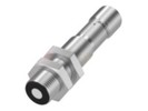
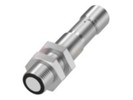
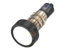
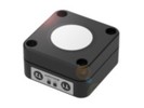
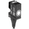
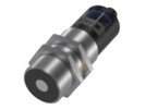
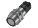
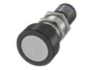
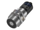
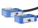
Choose an ultrasonic sensor by design and task
Ultrasonic sensor selection guide
Ultrasonic sensors help determine the presence of an object, distance or level height without contact. When choosing, the nearest and farthest position of the target, its ability to return sound and the required signal to the control system are decisive. Transparency or colour are not the main limitation, but no sensor can be considered a universal solution for every material and arrangement.
Reflection and time-of-flight measurement
A diffuse-mode sensor emits a short ultrasonic pulse and evaluates its echo. It determines the distance from the relationship d = c × t / 2, where c is the speed of sound and t is the time taken to travel to the object and back. Dividing by two is therefore not a calibration coefficient. At approximately 20 °C, c = 343 m/s can be used for an illustrative calculation. In the model, a distance of 0.5 m corresponds to the echo returning after about 2.9 ms; this alone does not determine the overall response of the device. The basics are also described in the microsonic explanation of the measuring principle.
The electronics need to recognise a sufficiently strong echo. The correct measuring principle therefore does not yet guarantee that the sound from a specific object will return to the receiver.
Blind zone and usable range
Immediately in front of the face of a conventional diffuse-mode version there is a blind zone. After transmitting, the transducer is still ringing and cannot reliably separate a close echo from its own excitation. Neither setting the switch point nor conversion in the PLC removes this physical limit. The nearest position of the object must remain outside it even with vibration and mounting tolerances.
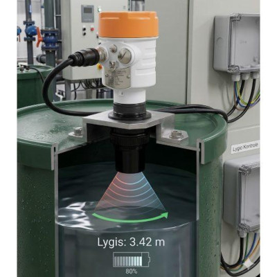
Assess the maximum range together with the test target used. The range stated for a well-reflecting surface is no guarantee of the same result on a thin edge. When measuring level, check both ends: an empty vessel must not be too far away and a full level not too close.
Sound beam, surface and inclination
The sound beam has a spatial shape. It is neither a thin line nor a cone with a universal angle. The detection diagram shows the behaviour for a certain target; the size, orientation and reflectivity of another target will change the usable area. Therefore also draw the edges of the tank, brackets and adjacent parts in the application sketch. They can create a competing echo even though they do not lie directly on the axis.
A smooth surface should be oriented approximately perpendicular to the measuring direction. When tilted, it can send the reflection to the side. A rough surface scatters sound, so it sometimes allows a greater inclination, but at the cost of a weaker return. Soft foams and porous materials can absorb sound significantly. A transparent film is therefore not automatically an easy target: waviness and position also matter.
For a liquid, verify the actual surface during operation, including foam and waves. Do not transfer the result from a calm surface to filling or agitation without testing. If the application requires a small measuring spot, also compare Distance sensors according to the specific principle and surface.
Temperature and environment
The speed of sound in air changes with temperature; near room temperature it is approximately 0.17 % per degree. Without compensation, the reported distance can therefore change even for a stationary target. Verify temperature compensation for the specific model. Moreover, the exact temperature of the entire sound path above a hot medium cannot be automatically derived from a local temperature measurement. Details are given in the Pepperl+Fuchs technical FAQ on environmental influences.
During verification, also monitor sensor warm-up after switching on, air blowing, condensation and deposits on the face. The degree of protection of the housing alone does not confirm the quality of acoustic measurement under these conditions.
Switching and analogue output
A switching output transmits a state, for example reaching a set limit. When switched, PNP sources current into the load from the positive supply, NPN sinks it to the negative pole. The wiring of the PLC input must correspond to this. NO/NC expresses the switching logic, not the type of transistor. Hysteresis separates the switch-on and switch-off conditions and helps limit switching near the limit.
An analogue output transmits a continuous value in a specified range, for example 0–10 V or 4–20 mA. It requires a corresponding analogue input and identical scaling. Voltage and current channels are not interchangeable. The designation "distance sensor" alone does not mean that every variant provides the PLC with a numerical distance.
Examples documented in the TECHNOLINE range
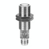
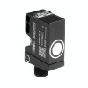
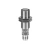
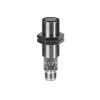
These data belong to the Lanbao models listed, not to the whole category. Datasheet UR18-CC35 states a blind zone of 0–30 mm, while dokumentace UR18-CM1 states 0–60 mm. A similar order code is therefore not enough to confirm interchangeability.
Electrical and mechanical compatibility
- Compare the supply range, current rating of the switching output and parameters of the control input. For analogue, check the permissible load, reference potential and supply method; the designation 4–20 mA alone does not prove a two-wire loop.
- According to the drawing, verify the thread, body length, space behind the connector and the possibility of aiming the face. The mounting thread is not automatically a sealing process connection.
- U Of cables and connectors for sensors, choose the correct version, number of contacts and pin assignment. An identical connector thread does not confirm identical wiring.
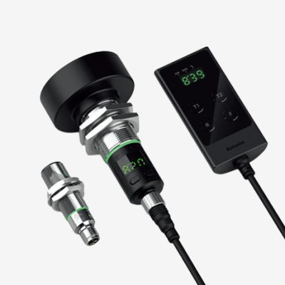
- Carry out Teach-in according to the manual of the exact order code. The teach wire need not be an additional output or synchronisation input.
Synchronisation and crosstalk between sensors
A sensor can pick up the pulse of an adjacent device or its reflection. Such acoustic crosstalk may only appear after the second part of the machine starts. First verify the prescribed spacing, orientation and reflecting surfaces.
Supported synchronisation coordinates measuring cycles. In simultaneous transmission mode, the devices work at the same time, which, however, may not allow an object to be unambiguously assigned to one sensor. Multiplex mode allocates measurements to the individual devices in turn; with their number, a longer update interval for each channel must be expected. The available modes, voltage levels and timing are determined by the manufacturer of the specific type. For the models in the table, synchronisation cannot be assumed just from the presence of Teach-in. The difference between the modes is explained by FAQ Pepperl+Fuchs k synchronizaci.
Model example: level from a 4–20 mA output
Consider a verified assembly in which 4 mA corresponds to a distance of 100 mm and 20 mA to a distance of 900 mm. This is a chosen model setting, not the factory configuration of the products listed. The conversion is d = 100 + (I − 4) × 800 / 16, with current I in mA and distance d in mm.
At 12 mA, d = 500 mm. If the sensor face is 1000 mm above the reference bottom, the level height is h = 1000 − 500 = 500 mm. Increasing distance here means a falling level. The highest level must still respect the blind zone and the reserve for waves. Assess the current on loss of echo according to the documentation; do not automatically convert it into a valid level.
Selection and verification procedure
- Record the extreme distances, the smallest target, its inclinations and the required response time.
- Choose a specific output and verify the PLC input, mounting and cabling.
- Test the actual material in the extreme positions, with temperature changes and with all adjacent sensors in operation.
- Record the settings, response and behaviour without a target. Assess the result according to the machine requirements.
Frequently asked questions and mistakes
Does Teach-in remove the blind zone?
No. It teaches evaluation limits within the usable range. Moving the target into the blind zone will not give a valid result.
Does fine resolution mean the same accuracy?
No. Resolution expresses the distinguishable step, repeatability the scatter under the same conditions and accuracy the deviation from the actual distance. Compare these data separately.
Why does the sensor work on the bench but fluctuate in the machine?
Check the inclination of the target, side reflections, air blowing and crosstalk. A practical test is to switch on adjacent sensors one by one with a stationary target. Stable cabling alone does not rule out an acoustic cause.
Help with choosing an ultrasonic sensor
For technical consultation, prepare the order code, extreme distances, material and size of the target, required response and PLC input. Kontaktujte technickou podporu TECHNOLINE with a description of the application or replacement.
Questions about choosing an ultrasonic sensor
What does ultrasound detect on a transparent or dark object?
Ultrasound evaluates sound reflection, so colour and transparency are not the main criterion. The size, inclination and surface of the target are also decisive. For films, foams or irregular objects, verify the echo return on an actual sample.
When to choose PNP/NPN and when analogue or IO-Link?
Use a PNP or NPN switching output for information about presence or exceeding a limit. For continuous distance, choose a compatible analogue input or a model with corresponding process data via IO-Link. Verify the available functions according to the complete order code.