Pneumatic accessories
Pneumatic accessories connect individual parts of the air circuit and help adapt its arrangement to a specific machine. When selecting, you need to know not only the part designation, but also both connected counterparts, the required function and operating conditions. A similar appearance of fittings or the same brand do not by themselves confirm interchangeability. This category is a signpost for line design, air distribution, flow adjustment and vacuum gripping.
Select the branch according to the task in the circuit
- Threaded fitting: connection to a specific threaded port of the equipment.
- Push-in fittings: selecting a connection for the corresponding pipe or tube.
- Bulkhead fittings: passing the line through a panel with resolved fixing.
- Reducing fittings: connecting different connection sizes.
- Flow control valves: flow adjustment taking into account the direction and function of the valve.
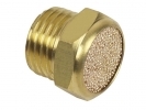
- Silencers: exhaust accessories, which are also selected according to flow requirements.
- Blanking plugs: closing the connection with a corresponding version.
- Blow gun: manual work with air according to the rules of the given workplace.
- Pneumatic suction cups: contact of the vacuum gripper with the surface of the handled part.
Three checks before ordering
Mechanical interface: record the full connection designation on both sides. For the tube, distinguish the outer and inner diameter; for the thread, its type, size and sealing method. Also check the space for mounting and service; the correct part may not be suitable for an installation that is too tight.
Function: draw where the medium should flow from and to. Connecting, branching, blanking, throttling and gripping are different tasks. For more complex accessories, compare the diagram and the full order code, not just the first part of the name.
Operating conditions: verify the permissible medium, pressure, temperature and environment for the specific version in the manufacturer's documentation. Assess use in vacuum separately. Do not derive the permitted range of the whole assembly from a parameter of one of its elements.
Model list of connection points
Let us consider four workstations, each with two separate lines. If each line forms one uninterrupted section, eight sections have a total of sixteen ends to connect. Dividing all eight sections into two parts adds eight intermediate fittings and sixteen more tube ends. This is our own inventory example, not a calculation of pressure loss or probability of leakage. It helps reveal missing counterparts and distinguish a spare piece from a part actually needed in the assembly.
Mounting and troubleshooting
Before intervention, shut down the equipment according to its instructions and secure it against unexpected movement. Disconnect lines only after safely removing pressure; for vacuum gripping, first secure the transported object. Take the mounting procedure, tightening and insertion check from the instructions of the specific accessory. After assembly, verify tightness, actual function and maintenance access during controlled commissioning.
In case of a leak, first determine its location, then check the counterpart, line size, seal condition and mechanical stress on the joint. In case of slow movement, monitor the whole supply and exhaust. Random replacement of one part without verifying the cause can leave the original problem in another part of the circuit.
FAQ
Can I replace a fitting based on a photo?
A photo helps determine the shape. For ordering, however, add dimensions, exact connection, function and operating limitations. For a replacement, record the original code and also compare the counterpart.
How to prepare documentation for selecting accessories?
Attach a simple circuit diagram, a list of connections, tube sizes and operating conditions. Mark what you already have and what should be part of the delivery; this makes the list and the compatibility check more precise.