

Base for 5 valves of series 300, TE4V-300M-5F, TECHNOLINE
Cat. no.: TE4V-300M-5F
Base for 5 valves of series 300
In stock 1 ks
25,79 €
excl. VAT · 31,20 € incl. VAT
Rate 24,43 CZK per 1 EUR. Prices are indicative, invoicing is in Czech crowns.
Base plates for valve terminals. Choose by valve series, number of stations and port.
Base for 5 valves of series 300
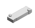
SY5000-26-1A-Q, blanking plate, for SY5000, SMC

TE4V-300M-3F TECHNOLINE – valve base. When selecting, verify the connection, size and other parameters of the specific variant.

TE4V-300M-4F, base for 4 valves of series 300, TECHNOLINE
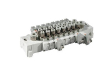
SS5Y5-60-09U-10-Q SMC – sub-plate. The exact variant is determined by the manufacturer's order code.
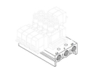
SS5Y5-42-02-C6F-Q, multiple sub-plate - aluminium, individual electrical connection, SMC
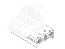
SS5Y5-20-10-00F-Q SMC – sub-plate. The exact variant is determined by the manufacturer's order code.

SS5Y-10-3832OBX, SMC, valve manifold. A manifold, base or connection block combines several pneumatic elements and distributes pneumatic or electrical connections in the assembly.
Prices include the recycling fee.
The base plate connects the valve positions with the supplies and working paths. Its choice determines the mechanical and pneumatic continuity of the assembly. The number of positions is not enough: verify the specified valve series, distribution of supplies and the required termination.
| Step | What to document |
|---|---|
| Identification | valve series and number of positions |
| Operating requirements | common or separate supplies |
| Acceptance | flow path map of each fitted position |
Plates for terminals include TE4V-300M, bases, SMC sub-plates SS5Y5,, the blanking plate SY5000-26-1A-Q and the item SS5Y-10-3832OBX. For ordering, first distinguish an empty base, a cover for an unoccupied position and an assembled manifold.
TECHNOLINE offers TE4V-300M-3F, TE4V-300M-4F a TE4V-300M-5F for three, four and five valves of series 300. The number of positions is only the first selection criterion. Attach the full designation of the valves and the required port arrangement to the enquiry so that the actual mounting interface can be compared.
SMC SY series catalogue for the SS5Y5-20 version, places the A/B working ports on the valves, for SS5Y5-42 in the base. The difference affects hose routing and the selection of fitted valves. The same series SY5000 therefore does not yet prove interchangeability of the plates. The catalogue also lists SY5000-26-1A-Q among the blanking plates of type 20; do not confirm its use just by a similar outline.
Prepare a table of positions starting from one clearly marked end of the base. Assign to each position the function in the machine, the valve order code, the working line and the control output. Mark spare positions separately. Such a plan allows the bill of materials, diagram and actual wiring to be compared without relying on the order of cables in the bundle.
Another decision concerns access during replacement. Draw in the sketch the space for disconnecting the hose, pulling out the connector and using a tool. Verify whether the marking of the end positions will be readable after installation. Describe the reserve for future expansion with a specific number of positions and connection requirements, not just a longer mounting rail.
Let us consider a hypothetical ten-station manifold. The design contains four single-coil valves and three double-coil valves; for this model, each valve occupies one station and each coil needs a separate control output. The number of occupied stations is 4 + 3 = 7, so 10 − 7 = 3 spare positions remain.
However, the number of required outputs is 4 × 1 + 3 × 2 = 10. Seven occupied stations therefore do not mean seven outputs in this design. Adding one more double-coil valve increases the configuration to eight stations and the requirement to twelve outputs. This arithmetic is not a specification of any offered plate or connector wiring, nor a confirmation of its expandability.
For an actual manifold, also verify the addressing method and the scope of delivery. The model counts only stations and commands; it does not include current load, space for additional modules, separate pressure branches or flow through the common supply. These questions require a separate check of the specific assembly before ordering.
SMC in SY mounting documentation distinguishes sealing assemblies and the prescribed orientation of components. When fitting, therefore, compare the position of channels, seals and fixing according to the exact type. Do not transfer the tightening torque between different screw sizes. Disconnect with the power supply off and pressure released according to the machine's service procedure.
As our own acceptance procedure, verify the individual branches according to the prepared table and record the command and the result. If one position has a problem, compare its configuration with the diagram; if several positions have a problem, check the common parts. The Valves and others Accessories always assess as part of a documented combination.
Before ordering, have the scope of delivery itemised: base, valves, blanking parts, seals and electrical connection. A general item name does not replace this bill of materials.
It is not enough. You need the series and the specific base type. For orientation in the related range, use the overview Pneumatic valves and then the documentation of the assembly actually ordered.
We need technical cookies for the cart and checkout to work — these are always used. Analytics cookies show us which pages people look for and where they get lost, and help us improve the shop. We only use them if you allow it. More in the data processing policy.
Choose which cookies we may use. You can change your choice at any time.
They keep the cart contents, your login and selected language, and protect forms from abuse. An order cannot be completed without them, so they are used even without consent.
Google Analytics shows us traffic and behaviour on the website in aggregated form. This tells us which pages are not working for people. We do not identify anyone from this data.