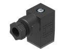
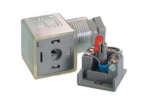
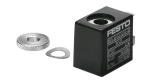
TE4V Coil AC230V, TECHNOLINE, valve coil
TE4V Coil AC230V TECHNOLINE – valve coil. When selecting, verify the connection, size and other parameters of the specific variant.
Rate 24,43 CZK per 1 EUR. Prices are indicative, invoicing is in Czech crowns.
SMC, Festo and TECHNOLINE pneumatic valves for controlling actuators – 3/2, 5/2 and 5/3 directional valves, base plates for valve terminals and accessories. Choose by function, port, actuation and coil voltage.
TE4V Coil AC230V TECHNOLINE – valve coil. When selecting, verify the connection, size and other parameters of the specific variant.
TE4V310-10-NC-DC24V-LD, valve 5/2 NC with spring and one coil power supply 24VDC, connection 3/8" with illuminated connector, TECHNOLINE
TE3V310-10-NC-DC24V-LD, valve 3/2 NC with spring and one coil, power supply 24VDC, connection 3/8 with illuminated connector, TECHNOLINE
TE4V310-10-NO-DC24V-LD, valve 5/2 NO with spring and one coil, power supply 24VDC, connection 3/8 with illuminated connector, TECHNOLINE
TE3V310-10-NO-DC24V-LD, valve 3/2 NO with spring and one coil, power supply 24VDC, connection 3/8 with illuminated connector, TECHNOLINE
Base for 5 valves of series 300
TE4V320-10-NC-DC24V-LD, valve 5/2 NC with spring and two coils power supply 24VDC, connection 3/8 with illuminated connector, TECHNOLINE
TE3V320-10-NC-DC24V-LD, valve 3/2 NC with two coils, power supply 24VDC, connection 3/8 with illuminated connector, TECHNOLINE
TE4V320-10-NO-DC24V-LD, valve 5/2 NO with spring and two coils, power supply 24VDC, connection 3/8 with illuminated connector, TECHNOLINE
TE3V320-10-NO-DC24V-LD, valve 3/2 NO with two coils, power supply 24VDC, connection 3/8 with illuminated connector, TECHNOLINE
TE4V330C-10-NC-DC24V-LD, valve 5/3 NC with spring and two coils, closed centre position, power supply 24VDC, connection 3/8 with illuminated connector, TECHNOLINE
TE4V330E-10-NC-DC24V-LD, valve 5/3 NC with spring and two coils, open centre position, power supply 24VDC, connection 3/8 with illuminated connector, TECHNOLINE
TE4V330C-10-NO-DC24V-LD, valve 5/3 NO with spring and two coils, closed centre position, power supply 24VDC, connection 3/8 with illuminated connector, TECHNOLINE
TE4V330E-10-NO-DC24V-LD, valve 5/3 NO with spring and two coils, open centre position, power supply 24VDC, connection 3/8 with illuminated connector, TECHNOLINE
VZOA-3-1/4 3464 SMC – Time-delay solenoid valve, Festo. When selecting, verify the connection, size and other parameters of the specific variant.
MSSD-EB, Festo, socket for solenoid valves, 151687. A pneumatic valve controls the direction, pressure or flow of the medium in a pneumatic circuit.
DXT152-25-1A SMC – mounting bracket for VT307. The exact variant is determined by the manufacturer's order code.
SY5000-26-1A-Q, blanking plate, for SY5000, SMC
SY7000-26-1A-Q, SMC, blanking plate for SY7000. A solenoid valve electrically controls the direction of compressed air flow.
A6 TECHNOLINE – transparent DIN connector, with status indication and surge suppressor 24V DC, SMC. The exact variant is determined by the manufacturer's order code.
X32 TECHNOLINE – DIN connector with status indication and surge suppressor 24V DC, SMC. The exact variant is determined by the manufacturer's order code.
A6-24V-V-R, SMC, connector. A cable or connector provides the electrical connection of specific elements of the equipment.
MSFG-24/42-50/60-OD Festo – solenoid coil, 34411. The exact variant is determined by the manufacturer's order code.
TE4V-300M-3F TECHNOLINE – valve base. When selecting, verify the connection, size and other parameters of the specific variant.
VDW22QAA, SMC, solenoid 2/2 valve, 24 V DC. A pneumatic valve controls the direction, pressure or flow of the medium in a pneumatic circuit.
Prices include the recycling fee.
The range includes SMC, Festo and TECHNOLINE pneumatic valves, including the TE3V/TE4V, SY, VQ, VX and VDW series. For selection, it is useful to separate the valve itself, its connection base and electrical accessories.
The designation 5/2 expresses five main ports and two positions; 5/3 adds a third position with a defined connection of channels. The specific Festo VUVG-LK10-M52-AT-M5-1R8L-S is a monostable 5/2 with internal pilot supply. In contrast, VUVS-L25-P53E-MD-G14-F8-1C1 has the 5/3 function with an exhaust centre position. The number of coils alone does not replace reading the pneumatic symbol.
Closing a single flow path is a different requirement. Separate SMC VDW documentation describes direct-operated 2-way valves and distinguishes variants by medium. Documentation VX21/22/23 similarly distinguishes versions for water, air and other media. Inclusion in the pneumatic category therefore does not by itself confirm the suitability of each item for any liquid.
For your own design, write down which branches should be pressurised and which exhausted for each command. In addition to the working cycle, describe a power failure, loss of air supply and restart. These are three separate situations; assess them according to the diagram of the specific valve and the whole machine.
Then compare the full order code, medium, required flow rate, working pressures and electrical connection. In the category Valves choose the functional version; Plates for terminals addresses the common arrangement of the assembly. For the decision, prepare a sketch of the actual line lengths, service clearances and consumer positions. Also record the measuring points for the acceptance test in the sketch.
Let us consider only a model assembly of eight hoses, each with an inner diameter of 6 mm and a length of 3 m. The geometric volume of one hose is V = π × d² × L / 4 = π × 0.006² × 3 / 4 = 0.0000848 m³, approximately 0.0848 litres. Eight hoses contain approximately 0.679 litres of internal space.
If each route is shortened to 1.5 m, the total drops to approximately 0.339 litres. The calculation compares only the geometry of two designs. It is not the free air consumption, switching time or parameters of the hoses or valves sold. For a time calculation, it would be necessary to add pressure conditions, the flow characteristic and the volume of the connected equipment.
Instructions SMC for VDW mounting require clean piping and prevention of sealing material entering the valve. When dismantling, it is necessary to disconnect the medium, release the pressure and switch off the power supply. A functional check follows assembly. Always take the specific mounting position and tightening from the documentation of the ordered version.
For the diagnostic record, compare the command, the voltage at the connected coil and the pressures upstream and downstream of the valve at the same moment. Record whether the fault occurs at the first switching, after warming up or during simultaneous operation of other branches. Such a distinction will help decide which part of the circuit to investigate further.
No. Compare the function, rest state, pilot version, medium and electrical equipment. The thread describes only one interface; also prepare the original diagram and the full order code.
Do not use the indicator light alone as acceptance proof of pneumatic function. Verify the actual response of the circuit. Select electrical parts in the category Accessories according to the exact version of the coil and connector.
We need technical cookies for the cart and checkout to work — these are always used. Analytics cookies show us which pages people look for and where they get lost, and help us improve the shop. We only use them if you allow it. More in the data processing policy.
Choose which cookies we may use. You can change your choice at any time.
They keep the cart contents, your login and selected language, and protect forms from abuse. An order cannot be completed without them, so they are used even without consent.
Google Analytics shows us traffic and behaviour on the website in aggregated form. This tells us which pages are not working for people. We do not identify anyone from this data.