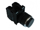
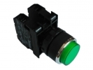
Push Button Switches
A push button switch is the interface between the operator and the control of the equipment. When selecting, the colour of the actuator is therefore not enough: first determine the meaning of the command, then the actuation method, the contact arrangement and the mounting. The range includes EMAS mechanical elements and Siemens illuminated push buttons, as well as electronic touch switches. Each group addresses a different part of the panel design. A short pulse to acknowledge a message, a permanently selected mode and light information about the equipment running are not one function, even though they may look similar on the front panel.
Start with the required behaviour
With a momentary push button, the mechanical action on the contact ends when it is released. If a short press is to trigger a longer process, its continuation is ensured by another circuit or program. With a latching push button, on the other hand, you expect the selected mechanical position to be maintained. Even this does not determine whether the equipment starts up after power is restored, waits for confirmation or switches to the default mode. This behaviour belongs to the control design and must be clearly described.
Double push button switches make it easier to enter a pair of related commands, but do not themselves create mutual interlocking. Mushroom push buttons offer a larger surface to press; neither the shape of the head nor the red colour is proof of an emergency stop function. Electronic Touch switches should in turn be selected according to the specific principle, output type and operating function. A mechanical contact and a semiconductor output should not be confused just because both pass on information about an operator action.
Size, shape and actual scope of the assembly
In the range you will find, for example, EMAS D100DDB with a rectangular front, D100KDY with a square front and D100YDY with a round front. The manufacturer classifies them as momentary elements with one normally open contact and a mounting size of 16 mm. The shape of the front is therefore not the shape of the mounting hole. See the EMAS D series overview by the manufacturer.
For light signalling requirements, distinguish Illuminated push buttons, mounting 22 mm and Illuminated push buttons, mounting 30 mm. The nominal mounting dimension is neither a complete cut-out drawing nor information about the external size of the head. Check the hole tolerance, panel thickness, any anti-rotation locking and the space behind the panel. The holder, contact block and light module must form an assembly supported by the manufacturer; the same diameter by itself does not guarantee their interchangeability.
Assess the contact and the light separately
The designation NO means a contact that is open in the basic, unactuated position; NC denotes a contact closed in this position. The specification 1NO + 1NC describes the contacts, not two independent confirmed machine states. When comparing, also consider the switching voltage, type of load, operating frequency and conditions for small signal currents. A higher current rating does not automatically guarantee better reliability when connecting a sensitive input.
The specific EMAS B190DY has an LED for 12–30 V AC/DC and one NO contact; for the contact, the manufacturer states 4 A at 250 V AC in category AC-15. These are two different electrical data in one assembly, not a universal supply voltage for the whole element. Documentation is available in technical sheet B190DY.
The utilization category expresses the switching conditions. The value for AC-15 does not entitle you to switch any DC load or to convert the current into motor power. For inductive loads, also address transients and the prescribed interference suppression. The selection of protection, wiring and verification of electrical safety are the responsibility of a qualified person according to the equipment design; this overview is not a guide to mains wiring.
In addition to EMAS, the range includes, for example, Siemens 3SU1102-0AB60-1BA0. The manufacturer describes a white flat momentary actuator with a holder, an NO contact and an integrated LED module. When ordering, the complete order code is therefore important, not just the brand designation or a photo of the front. See the Siemens product documentation.
Model example: what the light should really communicate
Consider an operator panel with three commands: a start request, message acknowledgement and a request to stop the normal process. The designer chooses three separate input signals and two light signals: “ready” and “run confirmed”. The model therefore needs three inputs and two control signals for the lights. This is not a bill of materials for a specific machine; some of the commands may be combined in a double push button, without automatically reducing the number of signals required.
Suppose that 0.8 seconds elapse between the start being received and the run being confirmed. The light marked “run” should not light up during this time just because of the press. Its meaning must be based on the actually monitored state. If the feedback does not arrive, a permanently lit command confirmation would confuse the operator. The example shows why the light logic is designed separately from the contact, even when they are under one actuator.
Mounting, handover and frequently asked questions
During mounting, check the completeness of the assembly, the seating of the seal, the prescribed tightening and the free movement of the actuator. Do not automatically transfer the protection rating of a specific element or its front to the terminals, cut-outs and the whole switchboard. Before handover, test the individual commands, their simultaneous actuation, power interruption and a mismatch between command and feedback. Create unambiguous labels for the operator that remain understandable even without colour coding.
For later servicing, record the complete code of the actuator and any separate modules. A photo of the coloured front usually does not capture the contact arrangement or the light supply. When replacing, therefore, go back to the bill of materials and the functional description, and then also verify the link to the program. A replacement that looks the same may transmit a different signal.
Do I need illumination for every push button?
No. If the status is clearly shown elsewhere on the panel, more suitable options may be Non-illuminated push buttons. The light should convey specific information, not just repeat the colour of the actuator.
Does latching solve the memory of the whole equipment?
No. Latching push button switches maintain the actuator position. Program memory, command validity and permission for a new start are separate design questions.