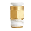
Straight fitting
A straight fitting provides a connection without a change of direction between the port and the tube. The range includes, for example, TPC08-G02, TPCF, miniature TPC with suffix C, metal TBPC/TBPCF and SMC KFG2H. Before selecting, determine the design of the tube connection.
Male and female threads are not the same connection
Pneuflex in separate sheets PC-G a PCF-G distinguishes the connection of a tube to a port with a female thread and the connection to a counterpart with a male thread. For PC-G, it also describes the external hexagon and the possibility of an internal tightening tool. Therefore draw tool access together with the tube direction.
A different design is SMC KFG2: the manufacturer's table distinguishes the outer and inner diameter of the tube and the mounting procedure works with a union nut. For the basic KFG2H0806-01, the combination 8/6 mm is stated; verify the offered variant with a suffix by the full code.
Selection according to interface and service access
Prepare a cross-sectional sketch of the connection: equipment port, sealing point, fitting and connecting tube. Add the exact designation for each part. For a short straight connection, check the possibility of pulling out the line axially; the surrounding wall can be an obstacle even if the fitting itself fits into the space.
When comparing variants, also ask about the supplied seal and the set of mounting components. If the dimension is decisive, require a drawing of the complete version including the position after screwing in. The length of the loose part, the mounting length and the space needed for the tool are assessed separately. For repeated service replacement, record their meaning in the bill of materials.
Model calculation: same outer dimension, different wall
Our own geometric example compares two hypothetical tubes with an outer diameter of 8 mm. The first has an inner diameter of 5 mm, the second 6 mm. With an ideal concentric cross-section, the wall thickness is t = (D − d) / 2. For the first variant t = (8 − 5) / 2 = 1.5 mm, for the second 1 mm.
The inner cross-section of the first tube is π × 5² / 4 = 19.6 mm², of the second π × 6² / 4 = 28.3 mm². The ratio is 36 / 25 = 1.44; the second cross-section is 44 % larger. This is our own geometry, not a value of an offered tube or an automatic guarantee of a higher flow rate.
The example explains why the selection sheet should contain the complete line dimension. It does not determine pressure resistance, stiffness or interchangeability of tubes. For a connection with a nut, the actual combination of dimension and material is compared with the manufacturer's documentation; for a push-in connection, its requirements are verified separately.
Mounting according to the specific design
For KFG2, the manufacturer prescribes inserting the tube into the removed union nut, pushing it into the body and first tightening the nut by hand. When tightening with a tool, the body is held with a second tool. The corresponding torque belongs to size KFG2; it is not a common mounting value for all straight connections.
Diagnostics without random replacement of parts
In your own service procedure, first determine the location of the fault and compile a record of the line used. In case of a recurring problem at the same inlet, compare the size, condition and prepared end of the tube. In case of a problem at the port, compare the threaded and sealing interface. Evaluate the repair in the same operating situation in which the fault was recorded.
FAQ
When does a straight version not fit spatially?
When the tube cannot be routed or pulled out for service in the required direction. Assess an alternative in the category Elbow fitting according to a sketch of the whole connection point.
Is the outer diameter value enough when ordering?
It depends on the design. For KFG2, the inner diameter and material are also verified. Basic orientation between different connections is provided by Threaded fitting.