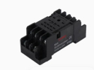
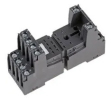
Sockets
A socket connects a plug-in relay to the wiring and determines the method of its mechanical fixing. When selecting, start with the exact designation of the relay for which you are looking for a base. The number of pins is only one piece of identification data. Alongside it, compare the layout of the terminals, their function, the terminal design and the accessories that are to remain part of the assembly.
Deciding according to the specific relay
This category includes, for example, GZM80, GZT4, GZT92, RS1P11G1 and PI6W-1P. The range also includes EMAS RS2.M2CO.08V.S0 and DYF14A. These codes do not represent one interchangeable series. Look for the switching part itself in the category Relay; when ordering the base, attach its complete designation including the variant.
RELPOL drawing for GZM80 specifies compatible families, terminals and accessories. External similarity therefore does not replace a comparison of the diagram or confirmation of a suitable clip.
When replacing an existing socket, create a terminal conversion list: function in the diagram, designation on the original base and designation on the new one. Do not confuse the view of the relay pins with the view of the base being wired. For each drawing, first find out from which side it is shown.
Principle of the load on the whole assembly
In the current assessment, record the relay, base, jumper element and connected circuit separately. A document for one component does not close the other rows. Request data for the same operating conditions; otherwise the lowest number in the table cannot be presented as the resulting load capacity of the whole assembly. Record the load type and temperature separately.
Author's model example: comparing limits
For a simplified exercise, assume three series-connected parts with limits of 8 A, 6 A and 5 A, all valid for the same model conditions. The preliminary common ceiling will not exceed 5 A. A higher figure on the first part does not transfer its reserve to the other components.
The figures are the author's, not parameters of the products offered. Even the calculated ceiling does not confirm the suitability of a specific load, protection or mounting. The example serves only to expose the error of labelling an assembly with the current of its strongest part. The actual assessment must include all conditions of the relevant manufacturer data.
Mounting the terminals and access to the relay
In the mounting documentation, state the type of conductor, its termination and the number of conductors in one terminal. Check the corresponding manufacturer data for the specific version. Do not take over the stripping length or tightening torque from another base. When laying out, maintain access to the terminals, labels and the space needed to remove the relay.
If the assembly requires a clip or a plug-in protective module, add their codes to the bill of materials. Verify suitable add-ons in relay accessories. The replacement part should also be identifiable when the wiring is complete; a photo of an empty socket does not replace the marking of the actually fitted assembly.
Diagnosing an intermittent connection
Record whether the fault changes after warming up, with vibration or after a service intervention. Divide the inspection record into the relay, insertion into the socket and the connected conductors. A specialist can then evaluate the specific fault location without randomly swapping components. Carry out handling and verification according to the procedure for safely secured equipment.
FAQ
Does the same number of pins mean interchangeability?
No. The function and geometry of the terminals must match, as well as the explicit compatibility of the relay and socket.
Can a missing clip be replaced by any clip?
Verify compatibility for the specific base and relay. External similarity does not prove correct retention of the whole assembly.