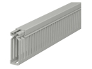
Cable trunking and DIN rails
Cable trunking organises conductors, a DIN rail is used for fixing compatible devices. Together, both elements create the layout of the control cabinet, but they perform different tasks. Therefore plan their dimensions together with the devices, terminals and cable entries. Complementary cable glands handle the entry into the enclosure and cable ties the local fixing of bundles; neither element replaces the route design itself.
Which material you are choosing
The range includes IBOCO T1-E trunking, for example in sizes 15 × 60, 25 × 40, 25 × 60, 40 × 40 and 40 × 60 mm. There is also a metal DIN rail PR-TS35/F5A with a nominal width of 35 mm. For each item, verify the supplied length, sales unit and the accessories stated in its description.
The manufacturer describes T1-E as control-cabinet trunking with narrow outlet slots and a cover; see the overview of the IBOCO T1-E series. Such a product must not be automatically confused with load-bearing cable trays for a building route. The intended use and mechanical design are as important as the numerical dimensions.
Usable space and access to conductors
The product of the nominal width and height is not automatically the usable area for cabling. Inside, the wall thickness, fixing, cover and actual arrangement of conductors play a role. When changing direction, you also need space for bending them. The design must allow the cover to be closed without compressing the insulation and allow access to the conductors during later modification.
Assess the rules for separating different circuits and the thermal conditions according to the whole equipment. The free volume of the trunking is not in itself proof of suitable joint routing. For servicing, it is often important to have clear access to the terminals and not to cover conductor labels or access to the operating parts of devices.
The rail must match the device
For a DIN rail, verify the profile, dimensions, fixing version and mechanical load. The same nominal width does not replace a check of the entire mounting geometry. The space for end clamps and accessories also belongs in the design, even though it does not carry the main device itself.
A protective bonding function cannot automatically be attributed to every metal rail and any device clips. If the rail has such a role, it must be designed and verified as part of the specific system. When cutting to length, edges and cleanliness of the mounting space must be taken into account so that processing the material does not damage the cabling.
Model layout example
Consider our own design with 600 mm of usable rail length. Twelve model devices each have a documented width of 18 mm, two end clamps take up 10 mm each and the project reserves 100 mm for future additions. What remains is 600 − 216 − 20 − 100 = 264 mm.
This remainder is not automatically space for further devices. The prescribed clearances, conductor bending, space between rows and access to fixings still need to be assessed. The dimensions in the example are given values, not a universal width of all modules or a recommended reserve for every control cabinet.
FAQ
Can I fill the trunking up to the cover?
Suitability is not decided just by whether the cover can be closed. You need an assessment of the layout, thermal conditions, bends and requirements for the installation in question.
Is a perforated rail always interchangeable with a solid one?
Not automatically. Compare the fixing method, mechanical requirements and device conditions. Perforation is only one of the design properties.