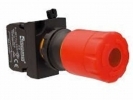
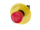
Emergency stop buttons for 22 mm mounting
What 22 mm mounting means
The mounting dimension refers to the panel hole, not the size of the red mushroom head. An actuator with a 30 or 40 mm head can therefore belong to the same mounting group. Before ordering, compare the hole drawing, panel thickness, anti-rotation method and space behind the panel. The front may look the same, yet the length of the contact assembly and the required mounting space differ.
Selection data – Push Buttons, 22 mm Mounting
| Step |
What to document |
| Identification |
hole, holder and contact assembly |
| Operating requirements |
contact function and release method |
| Acceptance |
mounting space and prescribed machine test |
Head, holder and contacts form an assembly
The range includes, for example, EMAS B200 and CP200 series components as well as Siemens SIRIUS ACT. Decide by the complete code and scope of delivery. The head operates the mechanism, the holder connects the individual parts and the contact block transmits the electrical signal. Distinguish between a normally closed NC contact, a normally open NO contact and documented positive opening. Neither the number of contacts nor the STOP label proves the suitability of the whole assembly for a safety function. Siemens documentation for the SIRIUS ACT series describes the link between the actuator and safe evaluation; these properties cannot be transferred to all items of another brand.
Release and restart
When choosing, compare turn-to-release, pull-to-release or key release, if offered by the version. Releasing the actuator and permitting a new start are two separate steps of the design. In the specification, write who may restart the equipment, from where, and what must be checked before starting. The machine's safety concept is decisive, not the convenience of the button itself.
Practical example of mounting space
A model assembly needs 48 mm behind the panel and another 20 mm for wire connection. The required space is at least 68 mm, even before assessing tool access and cable bending. An enclosure with a depth of 60 mm may therefore not be suitable, even though it has the correct hole. The figures are a teaching example; the actual dimensions are determined by the drawings of the selected parts.
Check before commissioning
Record the identity of all parts, their fastening, the contact diagram and the result of the functional test. Verify the behaviour on pressing, release and subsequent start according to the machine documentation. Resolve any discrepancy in marking or in the composition of the delivery before connection. The design and verification of the safety function are the responsibility of a competent expert; this guide serves to prepare the selection of components.
FAQ
Is the 40 mm figure in the name the size of the mounting hole?
Not necessarily. It is often the head diameter; check the mounting hole in the drawing.
Is the same red head enough for a replacement?
Also compare the contacts, mechanism, release, holder and documentation of the whole assembly.
Related selection: Push Buttons, 30 mm Mounting · Box + Push Button · Accessories.
Documents for further verification: manufacturer's documentation.