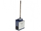
Metal Limit Switches L53
When designing the mounting of a metal switch L53 assess the entire space of the assembly. The outer dimension of the housing is just the beginning: you need the actuator reach, access to the fastening, space for the cable connection and the possibility of later service. A switch that can be fitted tightly into the machine may not be practically accessible for replacement or readjustment.
The contact variant belongs to the complete code
The public listing offers, for example, L53K13MIM311. Its EMAS sheet confirms a metal roller of 14 mm and snap-action contacts 1NO + 1NC. Selection by the first part of the name L53 would therefore leave the head and contact version unresolved.
When replacing, create a comparison of the original and new part: mounting base, head position, connection type, contact function and space for cable routing. Close each point separately. If only one item changes, an adjustment of the bracket, cam or wiring documentation may still be necessary.
Mounting envelope and service space
On the drawing, draw the cable gland with the cable and the space needed for the tool next to the housing. Mark the access for removing the cover or the whole product with a separate line. This reveals collisions in time that remain hidden when checking the catalogue dimensions of the switch alone.
For each cable entry, check how it is fitted or closed. Do not infer that the degree of protection is maintained just from the figure stated for the housing. The choice of cable, sealing accessories and mounting must correspond to the specific documentation; the general importance of correct sealing of the connection is pointed out in OMRON instructions for limit switches.
Author's example: why the housing dimension is not enough
Imagine a practice installation with a free depth of 92 mm. The model housing takes up 54 mm, the connection part 20 mm and the space prescribed in the model for cable routing another 15 mm. The total is 89 mm, leaving 3 mm.
If the connection part grows by 6 mm because of a different termination, the required depth rises to 95 mm. The installation no longer fits into the space, even though the housing dimension has remained the same. All dimensions are the author's own; they do not represent a drawing of L53K13MIM311 or the recommended cable bending radius.
The example can be extended to service access: the physical placement of the assembly does not yet say whether its joints can be loosened. The mounting check should therefore also include the possibility of carrying out planned service without stressing the cable and without accidentally changing the setting of adjacent parts.
What to record after mounting
Keep the bracket dimensions, the connection used and the reference position of the actuator. The functional check should include the approach and return of the cam. After replacement, compare the actual behaviour with the original record; the same order code does not mean that the bracket has not moved in the meantime or that the cam is not worn.
A common mistake when preparing a replacement is to choose an electrically similar product and deal with the mechanical conditions only during the shutdown. A sketch prepared in advance with the connection and access makes it possible to determine the necessary adjustments before the old assembly is dismantled.
Are identical contacts enough for interchanging with L51 or L52?
No. The electrical function is only one point of comparison. The drawing, actuator, permitted movement and mounting are also decisive.
Does a metal body guarantee resistance to any cleaning?
No. Assess the manufacturer's specific conditions, the seal materials and the finished connection.
For a design comparison, visit Metal Limit Switches L52 and the overview Metal Limit Switches IP65.