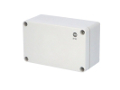
Plastic terminal boxes
A plastic terminal box must accommodate not only the connecting elements themselves but also the incoming cables and their terminations. A selection by length and width without checking the internal layout is usually incomplete. The current listing includes AG0811-S, PBT-4P, PBT-6P, Tibox TJ-10P and Famatel 68050 Solidbox. Use these names to identify the specific offer, not as a common specification for all boxes.
Start with a connection diagram
List the number of incoming cables, the number of their cores, cross-sections and the required connections. Each terminal needs its place, but access also requires the stripped conductor end and a mounting tool. Design the marking of the connections separately. For a service box, the diagram should be understandable even after a long time and without guessing which cable belongs to which device.
Transfer the actual internal obstacles to the drawing: lid posts, mounting points and any rail or base plate. Do not confuse the outer footprint with the usable floor area. Also check the height needed above the terminal where the lid closes. Prepared conductors should not become a mechanical support for the lid.
Material and environment
The Fibox material overview distinguishes polycarbonate and ABS and points out differences under UV exposure as well as the lack of inherent EMC shielding of these plastics. This is general documentation for asking the right questions, not confirmation of the material or resistance of a specific Tibox or Famatel model.
For the selected code, therefore verify the type of plastic, the conditions of use and the lid design. For placement near a machine, add information on cleaning agents, liquids and temperature. The designation “plastic” alone is not enough to decide on chemical resistance or permanent exposure to sunlight. If protection of a sensitive signal is needed, its solution must be part of the design of the cabling and the whole assembly.
Cable entries and sealing
For each cable, record the outer diameter and direction of approach. A gland is also selected according to its clamping range and mounting interface; the hole size is not the only parameter. Before laying out the entries, check whether their outer parts fit side by side and whether access to the fixing remains. Also take into account other connected parts that may restrict the space.
The protection rating of the finished assembly cannot be documented by simply copying the figure of the empty box. What matters are correctly chosen and fitted entries, sealed unused holes and the condition of the seals. The procedure for modifications and closing must be based on the documentation of the specific product. Electrical wiring and its inspection must be carried out by a qualified person.
Author's layout example
Imagine a usable width of 90 mm, a terminal assembly 50 mm wide and a requirement to leave 15 mm on each side for routing. 10 mm remains. This is only a model spatial sum: it does not verify hole spacing, minimum cable bending radius or tool access. Therefore draw the result into the actual drawing rather than automatically concluding that any box 90 mm wide is suitable.
What to check before ordering
Confirm whether terminals, a rail, a mounting base plate or glands are included in the delivery. A photo of a fitted example does not replace a bill of materials. For larger device assemblies, also compare control cabinet enclosure; replacing a small box with a larger one does not automatically solve all mounting requirements.
FAQ
Does the number in the name indicate the number of terminals needed?
Do not infer it without documentation. The number of connections follows from your diagram, while the commercial code may denote various product properties.
Is it enough to keep the same footprint when replacing?
Also compare the depth, internal mounting points, entries, lid and conditions of use. The same length and width do not confirm interchangeability.