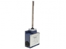
Metal Limit Switches IP65
A metal housing is a design choice, not a universal promise of resistance to impact, corrosion or cleaning chemicals. Above all, a limit switch must convert the cam movement into the correct electrical signal without excessive mechanical load. Therefore, in addition to the housing material, compare the actuator shape, approach direction, operating frequency and environmental conditions including the cable connection.
Plunger and roller solve different geometry
Specific models include EMAS L51K13PUM211 with a direct metal plunger. For it the manufacturer states snap-action contacts 1NO + 1NC, IP65 and a current of 3 A at 240 V AC in category AC-15. See technical sheet L51K13PUM211. The current rating cannot be freely converted to motor power or DC switching capacity.
Another model offered, L51K13MEP122 uses an adjustable lever with a plastic roller of 18 mm. The design is confirmed by the EMAS L51 series overview. A metal switch version therefore does not mean that all its parts are metal. The choice of roller surface can also be significant for contact with a specific cam.
To compare individual families, continue to Metal Limit Switches L51, Metal Limit Switches L52 or Metal Limit Switches L53. Verify the family selection against the dimensions, mounting and documentation of the specific variant; similarity of the code alone does not prove mechanical interchangeability.
How to assess the load on the assembly
With a plunger, the movement must act in the prescribed direction. A lever transmits movement via an arm, and extending it changes the geometric relationship between the cam movement and the rotation of the mechanism. Adjustment is therefore not just a way to reach a more distant obstacle. After changing the length or angle of the lever, check the switching point, permitted overtravel and return during the reverse movement again.
A rigid cover does not solve a flexible bracket or cam vibration near the switching point. The mechanical stop of the drive should take up the forces by a designated structural element, not by the limit switch. For the electrical part, distinguish between snap-action, slow-action and possibly overlapping contacts according to the diagram of the specific variant; identical dimensions do not mean identical timing.
Model example: the actual number of operating cycles
Consider a station with twelve operating cycles per minute, an eight-hour shift and 250 working days per year. If each cycle involves one complete actuation and release of the switch, the result is 12 × 60 × 8 × 250 = 1 440 000 such cycles per year. If the same switch is operated twice per cycle, the number would rise to 2 880 000.
This is the author's estimate of operating load, not a prediction of the service life of L51. For the manufacturer's service life, distinguish between mechanical and electrical test conditions and the method of counting operations. Frequency, switched load, environment and impacts should be compared with the documentation of the selected model; simply dividing the catalogue number of operations by the annual total does not guarantee a service interval.
Mounting and frequently asked questions
During installation, check the prescribed electrical protective measure, cover fastening, seal condition and cable entry. Ensure cable strain relief and that cable pull does not change the position of the switch. If water ingress is significant, compare Limit Switches with Higher IP67 Protection; alternative housings can be found in the category Plastic Limit Switches IP65.
Does a metal version mean a stainless steel design?
No. The material and surface finish must be determined for the specific part. The category name does not prove suitability for a corrosive environment.
Can the original setting be kept with a different head?
This cannot be assumed. Even a compatible head may change the arm, direction of action and movement reserve. After replacement, the operating cycle must be checked again.