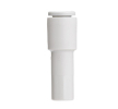
Reducing fittings
Select reducing fittings according to all connected interfaces. The range includes straight versions, reduced T-fittings, manifolds and SMC plug-in reducers. A pair of dimensions in the designation is not enough to draw the whole assembly. For three or more ports, you must also determine where the larger connection is and where the individual branches should continue.
Pneuflex for PG states a coaxial connection of two tubes of different diameters. SMC KQ2R04-06A connects a tube with an outer diameter of 4 mm with a plug-in end into a fitting of size 6 mm.
Pneuflex for PGE describes a larger middle port and smaller coaxial ends; for PEG the middle port is smaller than the coaxial ends.
Port map before ordering
Our own selection procedure uses a sketch with ports A, B and possibly C. For each, add the connection type and size. Separate the tube outer diameter for choosing the connection from the inner diameter for the cross-section balance. If you need a plug-in adapter into an existing fitting, compare Barb fittings. For simply splitting lines of the same size, continue via Branch fittings.
Our own design question is: is the smaller line a short transition at the consumer, or a long common route? Record these situations separately. In the specification, record the length of both sections, the required consumption and operating conditions. Do not assess the replacement only by the outer outline of the adapter; you also need a distribution diagram so that the change of size is not transferred to a different branch than intended.
For reduced branching, compare two variants of your own diagram: a single part with the required port map and a standard branch fitting supplemented with separate transitions. In the second variant, draw each added part and service access to it. The decision should not be based only on the number of components; it must preserve the correct assignment of sizes to consumers and space for possible replacement of an individual branch.
Our own model of cross-sections and velocities
Let us assume model inner diameters of 8 and 5 mm and a local volumetric flow rate of 9 litres per minute, considered in both cross-sections under the same conditions. The areas A = πd²/4 are approximately 50.3 and 19.6 mm². The flow rate corresponds to 150 000 mm³/s, so the velocities Q/A are about 2.98 and 7.64 m/s. Their ratio is 8²/5² = 2.56. This is our own simplified example, not a flow characteristic of the fitting or pressure dimensioning. For actual compressed air, it is necessary to distinguish the local volumetric flow from the flow converted to reference conditions; a change in pressure and temperature changes the calculation input.
Mounting according to individual interfaces
Prepare the work for a safely secured section being changed without pressure. For your own mounting check, mark the smaller and larger interface in the sketch and on the line. For branching, check all ports one by one so that the correct size is not assigned to the wrong branch. For the plug-in version, record the receiving fitting separately. If you do not need a transition, compare the simpler diagram in the category Straight fittings.
Pneuflex for PG states inserting the tube and removing it after pressing the collet. For each end, verify that you have assigned the correct size in the sketch.
Diagnostics during consumption
Your own service record should state at which consumption the problem appears and which section was changed. Compare the same working conditions before and after replacement. If the line was shortened or the branching changed at the same time, do not evaluate the result as the effect of the reducer alone. First separate changes in route, cross-section and the specific connecting part.
FAQ
Does a larger size always mean the inlet?
Mark the actual use of the ports in your own diagram. Do not infer the flow direction or the orientation of all branches from a mere pair of sizes.
Can performance be determined by the ratio of diameters?
The ratio of cross-sections helps compare your own model. For actual operation, you need the data of the selected item and the conditions of the whole distribution, including consumption and line lengths.