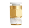
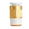
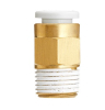
TBPC04-M6, TECHNOLINE, all-metal straight push-in fitting, tube Ø4mm, male thread M6
TBPC04-M6, TECHNOLINE: straight push-in fitting; tube Ø4mm, male thread M6. Push-in connection for pneumatics.
Rate 24,43 CZK per 1 EUR. Prices are indicative, invoicing is in Czech crowns.
Threaded fittings for connecting pneumatic tubes to valves, cylinders and air preparation units – straight, elbow and branch. Choose by tube diameter and thread.
TBPC04-M6, TECHNOLINE: straight push-in fitting; tube Ø4mm, male thread M6. Push-in connection for pneumatics.
TBPC04-G02, TECHNOLINE: straight push-in fitting; tube Ø4mm, male thread G1/4. Push-in connection for pneumatics.
TBPC06-M5, TECHNOLINE: straight push-in fitting; tube Ø6mm, male thread M5. Push-in connection for pneumatics.
KQ2H04-01AS, SMC: straight push-in fitting with male thread; tube Ø4mm, thread R1/8. Dimensions and use according to the catalogue series.
TBPCF04-G01, TECHNOLINE: straight push-in fitting with female thread; tube Ø4mm, female thread G1/8. Push-in connection for pneumatics.
TBPC06-M6, TECHNOLINE: straight push-in fitting; tube Ø6mm, male thread M6. Push-in connection for pneumatics.
KQ2H06-01AS, SMC: straight push-in fitting with male thread; tube Ø6mm, thread R1/8. Dimensions and use according to the catalogue series.
TPCF06-G04, TECHNOLINE: straight push-in fitting with female thread; tube Ø6mm, female thread G1/2. Series 0–10bar, 0 to +60°C. Push-in connection for pneumatics.
TPCF08-G01, TECHNOLINE: straight push-in fitting with female thread; tube Ø8mm, female thread G1/8. Series 0–10bar, 0 to +60°C. Push-in connection for pneumatics.
TPCF10-G01, TECHNOLINE: straight push-in fitting with female thread; tube Ø10mm, female thread G1/8. Series 0–10bar, 0 to +60°C. Push-in connection for pneumatics.
TBPCF04-G02, TECHNOLINE: straight push-in fitting with female thread; tube Ø4mm, female thread G1/4. Push-in connection for pneumatics.
TBPCF04-M5, TECHNOLINE: straight push-in fitting with female thread; tube Ø4mm, female thread M5. Push-in connection for pneumatics.
TBPCF06-G01, TECHNOLINE: straight push-in fitting with female thread; tube Ø6mm, female thread G1/8. Push-in connection for pneumatics.
KQ2H06-M5A, SMC: straight push-in fitting with male thread; tube Ø6mm, thread M5. Dimensions and use according to the catalogue series.
TBPCF08-G01, TECHNOLINE: straight push-in fitting with female thread; tube Ø8mm, female thread G1/8. Push-in connection for pneumatics.
TPCF08-G03, TECHNOLINE: straight push-in fitting with female thread; tube Ø8mm, female thread G3/8. Series 0–10bar, 0 to +60°C. Push-in connection for pneumatics.
TPCF10-G02, TECHNOLINE: straight push-in fitting with female thread; tube Ø10mm, female thread G1/4. Series 0–10bar, 0 to +60°C. Push-in connection for pneumatics.
TBPCF04-M6, TECHNOLINE: straight push-in fitting with female thread; tube Ø4mm, female thread M6. Push-in connection for pneumatics.
TBPCF06-G02, TECHNOLINE: straight push-in fitting with female thread; tube Ø6mm, female thread G1/4. Push-in connection for pneumatics.
KQ2S23-M3G, SMC: straight fitting with internal hexagon and male thread; tube Ø3.2mm, thread M3. Dimensions and use according to the catalogue series.
KQ2S04-M5A, SMC: straight fitting with internal hexagon and male thread; tube Ø4mm, thread M5. Dimensions and use according to the catalogue series.
TPCF08-G04, TECHNOLINE: straight push-in fitting with female thread; tube Ø8mm, female thread G1/2. Series 0–10bar, 0 to +60°C. Push-in connection for pneumatics.
KQ2H08-01AS, SMC: straight push-in fitting with male thread; tube Ø8mm, thread R1/8. Dimensions and use according to the catalogue series.
TPCF10-G03, TECHNOLINE: straight push-in fitting with female thread; tube Ø10mm, female thread G3/8. Series 0–10bar, 0 to +60°C. Push-in connection for pneumatics.
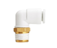
KQ2L04-M3G, SMC: elbow push-in fitting 90°; tube Ø4mm, thread M3. Dimensions and use according to the catalogue series.
Prices include the recycling fee.
A threaded fitting connects the tube distribution to a connection point of the equipment. The range includes the Pneuflex TPC, TPL, TPB and TPD families, their miniature or metal versions and various SMC designs. Selection starts by determining both sides to be connected.
Pneuflex manufacturing sheet PC-G describes a direct connection of a tube to a female threaded port. The threaded side of this version uses a sealing O-ring; the manufacturer does not require additional PTFE tape here. Therefore determine the sealing method according to the specific design and seating point.
Pneuflex mounting instructions distinguishes the retention of the tube by holding elements and its sealing in the adjoining ring.
In the selection sheet, record separately the port designation, thread size and type, tube size, medium and operating conditions. Add a photo of the original part and its full code. For a threaded joint, also compare the space for the seal and tool access. A similar outline or the same release ring colour is not a sufficient basis for an order.
According to the intended routing, continue to the categories Straight fitting, Elbow fitting or Branch fitting. Add the distances from the surrounding walls and the space needed for service disconnection to the sketch. Distinguish the state during mounting of open equipment and later access after it is covered. It must be possible not only to fit the part, but also to check and replace it.
For our own model, let us consider twelve connections, each with one straight fitting between the threaded port and the tube. In this simplified sketch, we record two external joint interfaces per connection: the threaded joint and the tube connection. In total there are 12 × 2 = 24 points for acceptance inspection.
The second model variant inserts a separate threaded adapter into each connection. Assuming one more joint per adapter, there are 12 × 3 = 36 inspected interfaces, i.e. twelve more. The number increases by 50 %. The result describes only this specifically drawn topology; it does not determine the probability of leakage, flow rate or service life of the product.
In the bill of materials, therefore, mark which adapters address an actual need and which arose only from gradually adding replacements. Also compare both variants according to service availability and the required line direction. A smaller number of joints alone does not determine the suitability of the assembly if it does not match the port, mounting space or operating requirements.
In its instructions, Pneuflex requires zero internal pressure before pulling out the tube. Do not transfer the push-in connection procedure to designs with a union nut.
For your own diagnostic record, mark each interface and, during an approved test of the assembly, monitor where the leak actually appears. Separate the location at the port from the tube inlet. Record the state at rest and during the working cycle and record previous service interventions. In case of a recurring fault, compare the complete combination of port, fitting and line.
The full code of the original part, port and tube designation, a photo of the sealing point and a sketch of the available space. Also state the medium and working conditions so that the selection is not based only on appearance.
The chosen sealing method must correspond to the documentation of the part and the port. When replacing, record how the original joint was sealed and verify the prescribed procedure before mounting.
We need technical cookies for the cart and checkout to work — these are always used. Analytics cookies show us which pages people look for and where they get lost, and help us improve the shop. We only use them if you allow it. More in the data processing policy.
Choose which cookies we may use. You can change your choice at any time.
They keep the cart contents, your login and selected language, and protect forms from abuse. An order cannot be completed without them, so they are used even without consent.
Google Analytics shows us traffic and behaviour on the website in aggregated form. This tells us which pages are not working for people. We do not identify anyone from this data.