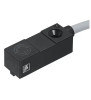
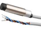
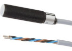
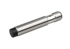
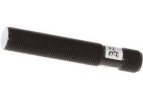
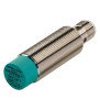
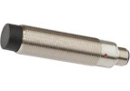
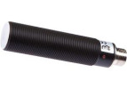
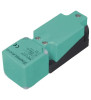
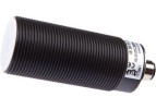
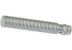
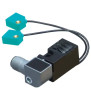
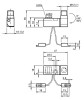
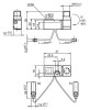
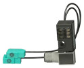
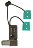
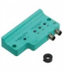
Weld-immune inductive sensors do not switch due to the strong magnetic field of welding currents and have a spatter-resistant surface. They are designed for welding fixtures and robotic cells. Choose by diameter, range and cable design.
An inductive sensor for welding operations is chosen according to magnetic fields, metal spatter, temperature and mechanical stress. A single declared resistance does not cover all influences. Reliable position detection of the fixture must also be verified during actual welding.
LANBAO LR18A-Y. Source: LANBAO, manufacturer. Original product image from the manufacturer. Check the design and connection according to the order code.
Four different causes of failures
Environmental influence
Typical symptom
Selection requirement
Magnetic field during welding
Signal change exactly while the welding current is flowing.
Declared resistance to the type and intensity of the field at the given position.
Spatter and adhering metal
Deposits on the face, surface damage or permanent switching.
Suitable surface, protected location and access for cleaning.
Thermal load
Failure after heating up or gradual damage to the cable.
Limits of the head, cable, connector and any cover.
Movement and mechanical stress
Intermittent signal, change of gap or cracked cable.
Cable strain relief, suitable bending radius and a rigid bracket.
Assess resistance to magnetic fields for the specific conditions of the welding equipment. The orientation of the sensor, the distance from the current path and the routing of power cables can change the result. General industrial electromagnetic immunity alone does not confirm suitability for every location in a welding fixture.
Anti-spatter surface and the Factor 1 property
For the LR18A-Y series, LANBAO specifies a PTFE surface finish to reduce adhesion of welding spatter and an approximately uniform material factor. These are different properties: the surface helps with contamination, while the material factor addresses behaviour towards metal targets. Verify the exact scope of resistance for the ordered variant.
The coating is not unlimited protection against impact or temperature. A damaged surface can make it easier for particles to adhere. Do not clean it with a tool or chemical agent not permitted by the manufacturer. If possible, place the active part outside the direct path of spatter while keeping the correct detection geometry.
Mounting and cabling in the fixture
Leave a margin against collision with the part and the clamps. Route the cable away from hot surfaces, sharp edges and snag points. Separate signal lines from power paths according to the equipment manufacturer's rules. Design shielding and earthing for the specific assembly; additional random bonding of metal parts may not eliminate interference.
A protective cover must not introduce metal into the prohibited zone in front of the face. At the same time, it can impair cooling or trap deposits. Therefore verify every change of cover or bracket in terms of both switching and temperature.
Test during an actual welding cycle
Check the position and electrical signal of the fixture before welding.
Monitor the output while the current is switched on, during the weld itself and during subsequent cooling.
Try all welding modes used and the extreme positions of the mechanism.
Compare the sensor indicator with the PLC input record and the supply status.
After a normal production interval, check deposits, surface and cable; determine the cleaning interval.
If the fault occurs only when the welding current is switched on, start by diagnosing the field and the electrical path. If the state remains faulty even after welding and improves after cleaning, check metal deposits and the working gap. This procedure helps you choose an effective measure.
FAQ
Is every Factor 1 sensor suitable for welding?
No. Material compensation alone does not confirm resistance to welding fields, spatter or temperature.
Will a metal protective cover solve all problems?
No. It can affect the active field or retain heat and dirt. Its geometry and effect must be verified according to the mounting rules.
What should I send to choose a replacement?
The order code, a photo of the installation, the working gap, the target material, the welding mode and a description of when the failure occurs. Add the required electrical wiring and the ambient temperature.
For a specific selection, prepare the material and dimensions of the target, the working gap, the environmental conditions and the required electrical connection. An overview can be found in the categories Special sensors and Inductive sensors.
Technical documents:LANBAO: LANBAO LR18A-Y. This guide helps with selection; binding parameters, wiring and mounting are defined by the documentation of the ordered model.
Cookies on this website
We need technical cookies for the cart and checkout to work — these are always used. Analytics cookies show us which pages people look for and where they get lost, and help us improve the shop. We only use them if you allow it. More in the data processing policy.
Cookie settings
Choose which cookies we may use. You can change your choice at any time.
Technical cookies
Always active
They keep the cart contents, your login and selected language, and protect forms from abuse. An order cannot be completed without them, so they are used even without consent.
Analytics cookies
Google Analytics shows us traffic and behaviour on the website in aggregated form. This tells us which pages are not working for people. We do not identify anyone from this data.