Vacuum ejectors
A vacuum ejector creates vacuum using compressed air. When selecting it for handling, the highest achievable vacuum is not enough: the evacuation of leaks, gripping time, air consumption and control method are also decisive. The force is not created by the value in the ejector catalogue itself, but by the pressure difference acting on the effective area of the suction cups in the actual circuit.
Versions offered and their differences
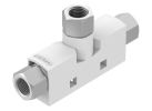
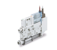
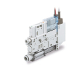
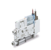
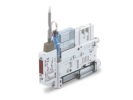
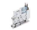
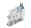
In this category you will find, for example, Festo VN-10-H-T3-PI4-VI4-RI4 and SMC ZK2, assemblies including ZK2B15R5NL2A-08, ZK2B12R5NL2A-06 and ZK2A10K5RWA-06. When comparing, separate the pneumatic function itself from the equipment for switching air, releasing the part and evaluating the vacuum. These functions and their electrical design cannot be inferred from the common series name alone.
Festo datasheet for VN-10-H-T3-PI4-VI4-RI4, number 193500, specifies a working pressure of 1–8 bar, a maximum vacuum of 89 % and a maximum suction flow to atmosphere of 25 l/min. The pressure for maximum suction flow is 3.1 bar, for maximum vacuum 4.5 bar. These are different operating points, not a promise that all maxima are achieved at the same time.
U SMC ZK2A10K5RWA-06 the manufacturer specifies a 1.0 mm nozzle, 24 V DC power supply, one PNP output, a vacuum port for a 6 mm hose and NC supply and release valves. This variant has an air-saving function. Before replacing, compare the full code and the wiring; a different suffix may mean a substantially different configuration.
Air, piping and reaching the working vacuum
First determine whether the product is impermeable, porous or variable. For a tight part, the main concern is evacuating the volume and maintaining the vacuum; with leakage, suction must continuously compensate for the inflow. Assess the suction flow at the required vacuum; a value relative to atmosphere does not replace it. Moreover, compressed air consumption is not the same as the amount of air sucked in.
A long hose increases the evacuated volume and adds resistance when air flows. Narrow passages, a clogged filter or an unsuitable fitting have a similar effect. Therefore, distinguish between the vacuum at the ejector and at the suction cup. A persistent pressure difference along the line is related to flow; in a tight, steady system without flow, the same loss as during evacuation cannot automatically be assumed.
Prepare the supply using suitable pneumatic air preparation units and measure the pressure while other consumers are drawing air. A setting that is too high is not a universal means of faster gripping. During mounting, keep the prescribed exhaust path and access to the filters; during acceptance, verify the time from the command to the confirmation of gripping and the reliable release of the part.
Model force calculation including losses
The following calculation is our own simplified example, not a parameter of the supplied assembly. Two suction cups with an assumed effective diameter of 40 mm lift a horizontal non-porous part vertically upwards. Total effective area A = 2 × π × 0,04² / 4 = 0.002513 m². The actual effective diameter must be provided by the suction cup manufacturer; it may not be equal to the outer dimension.
With a pressure difference of 60 kPa, the theoretical force would be F = Δp × A = 150.8 N. However, let us consider a model loss of 10 kPa during flow, so that 50 kPa remains at the suction cups: the force drops to 125.7 N. Furthermore, purely for this example, we choose a coefficient for area utilisation and load distribution of 0.8. The usable value is then 100.5 N. The coefficient does not replace measurement or data on the specific suction cups.
For a mass of 3 kg, an upward acceleration of 2 m/s² and the design factor of 2 chosen here, we require 2 × 3 × (9.81 + 2) = 70.9 N. In this model, the reserve is approximately 29.7 N. However, a drop in the pressure difference at the suction cups to 30 kPa would reduce the usable force to 60.3 N and the condition would not be met. The decision limit must therefore include a reserve for a further drop and for the response time.
Schmalz, in the technical data of suction cups, distinguishes between the theoretical normal force and the conditions of actual contact. Our calculation does not address lateral load, friction, peeling or an offset centre of gravity. For a vertical wall or sharp lateral acceleration, the same comparison cannot be adopted without changing the model.
FAQ when selecting
Will a more powerful ejector solve a leaking suction cup?
It can increase suction, but it does not guarantee suitable gripping. First verify the shape, surface, seating and required flow at the working vacuum. Otherwise you will only increase consumption without sufficient reserve.
Where to confirm that vacuum has been reached?
For process confirmation, measure a representative vacuum of the gripping circuit. Look for a suitable version among pressure switches and verify its range for vacuum. A single value upstream of a common branch may not reveal a problem with an individual suction cup.
Will the part remain held if the air supply fails?
This cannot be promised without verifying the specific circuit. The valves, leakage, volume and condition of the suction cups are decisive. Neither the ejector nor a normal vacuum confirmation is in itself a safety device against a falling load.
If you cannot find the required ejector in our range, contact us with the full designation, a description of the application and the required interface.