Shock Absorbers
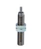
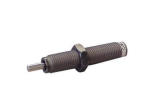
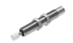
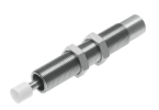
Choose a shock absorber according to the energy of the moving mechanism and the frequency of its stops, not just according to the thread. Two conveyors with the same mass may need a different shock absorber if they have a different speed or if the drive keeps pushing during braking. The range includes hydraulic versions from SMC and Festo, which must be assessed according to the specific designation and working conditions.
How to navigate the range here
The catalogue includes, for example, SMC RBC1007, RBC1412, RBC2015 and RJ1007HN as well as Festo DYSW-8-14-Y1F and DYSW-10-17-Y1F. These models are not substitutes for each other based on a similar diameter. The stroke, characteristic, mounting geometry, permitted load and the space needed for the piston rod return are decisive. When repairing, first write down the full designation of the original part and measure the actual arrangement of the stop.
Festo for DYSW-8-14-Y1F, number 548073, specifies stroke 14 mm, self-adjusting soft characteristic, energy of at most 4 J per stroke and 21 000 J per hour. The maximum impact speed is 3 m/s. These values apply to this model, not to the whole category.
Even within one series the differences are significant: SMC RB/RBC table specifies for RBC1007 an energy of 5.88 J, a stroke of 7 mm and at most 70 cycles per minute; for RBC1412 an energy of 19.6 J, a stroke of 12 mm and at most 45 cycles per minute. A higher energy per impact therefore does not automatically mean a higher permitted frequency.
What to find out before sizing
Write down the moving mass, the speed just before contact, the usable braking stroke and the force that the drive adds during braking. For pneumatic cylinders switching off the control signal is not necessarily the moment the force disappears. It depends on the wiring, the pressure in the chambers and the course of exhaust. Regulation using pneumatic air preparation units can help stabilise the input conditions, but does not by itself replace the energy calculation.
SMC selection procedure takes into account both the kinetic energy and the work of the driving force and requires a check of further operating limits. For your own design, distinguish free run-out from stopping a still-driven system. When moving downwards, the work of gravity is added; for a rotary mechanism, start from the moment of inertia and the impact geometry, rather than substituting the whole mass without further consideration.
Model calculation of energy and cycles
Consider our own illustrative example of a horizontal carriage: moving mass 4 kg, speed 0.8 m/s, persisting driving force 80 N and use of the full stroke of 14 mm. We consider the force constant, neglect friction and assume one impact per working cycle. None of these input values is data about a specific customer machine.
The kinetic energy is Ek = ½ × 4 × 0,8² = 1.28 J. The work of the drive during compression is Ep = 80 × 0.014 = 1.12 J. In our simplification, the shock absorber must therefore absorb 2.40 J per impact. With a variable driving force, its work would be determined from the force curve over the travel, not from a single product.
At 30 impacts per minute, there are 1 800 impacts per hour and the energy load is 2.40 × 1 800 = 4 320 J/h. At 150 impacts per minute, the result is already 21 600 J/h. The second variant exceeds the hourly value of the specified DYSW-8-14-Y1F, even though the energy of a single impact remains below 4 J. The candidate must therefore be rejected for this assumed continuous mode, not approved based on a single value.
Speed is just as important: if it doubles to 1.6 m/s, the kinetic energy increases four times to 5.12 J. With unchanged drive work, this results in 6.24 J per impact. However, even the first, slower variant is not a finished approval of the design; the forces, return, mounting and the relevant selection conditions still need to be verified.
Mounting, operation and FAQ
Design the contact so that the load corresponds to the permitted direction of action of the specific shock absorber. Verify alignment, bracket stiffness, end stop position and thread locking according to the mounting instructions. A flexible frame can change the actual stopping behaviour. During testing, gradually increase speed and frequency, monitor temperature, piston rod return and changes in behaviour; do not jump straight to the fastest production cycle.
Is it enough to stay within the maximum energy of one impact?
No. Repetition, thermal load, speed, acting force and the time to return to the initial position are assessed separately. Breaks between series are not an automatic substitute for verifying the permitted operating mode.
Is the energy distributed evenly between two shock absorbers?
Only if the design and the actual simultaneity of contact correspond to this. A small deviation can load the first shock absorber earlier. Dividing the energy by two without checking the geometry is not a sufficient design.
Can the shock absorber be used as a safety end stop?
Selecting a standard industrial shock absorber alone does not prove a safety function. Protection against hazardous movement and behaviour in the event of a fault must be addressed by the design of the entire equipment.