Ceny zawierają opłatę recyklingową.
Frequency inverter accessories: speed setpoint and operator panels
Command, setpoint and actual speed
The accessories in this category are used mainly for entering values and operating the inverter. Distinguish between run enable, frequency request and actual motor speed. A potentiometer creates a setpoint; turning it alone does not prove that the motor has reached the required speed. When choosing, start with the inverter input type and the way the operator will enter commands.
Selection data Frequency Inverter Accessories
| Step |
What to document |
| Identification |
inverter type and its control input |
| Operating requirements |
power supply and setpoint range |
| Acceptance |
signal, scaling and inverter response |
Three different product groups
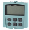
The listing includes the TAYEE LA42DWQ-22 10K, mechanical potentiometer, ENDA EDP2041 digital potentiometers and the Siemens 6SL3055-0AA00-4BA0 panel for S120. A potentiometer connected to an analog input is not a universal replacement for a communication panel. For EDP2041, ENDA distinguishes analog outputs and communication options. Confirm the power supply and equipment according to the full order variant, especially for versions with the RS suffix.
Analog range and scaling
At the inverter input, both the signal type and its range must match. Voltage and current inputs have different wiring and settings. Write down the lower and upper signal values and the corresponding frequency. Also determine the behaviour in the event of a cable break, power failure and restoration of operation. Memory of the last value, ramps and start enable are separate system properties.
Teaching example of scaling
In the model, we set the input 0–10 V as a request of 0–50 Hz. A signal of 6 V corresponds to 30 Hz. If the same input represents the range 20–50 Hz, 6 V corresponds to 20 + 0.6 × 30 = 38 Hz. The same potentiometer can therefore lead to a different command depending on the inverter parameter setting. The numbers do not define the properties of a specific item or the mechanical speed of the motor.
Checking the connection and replacement
Prepare the inverter type, the input diagram, the accessory power supply and the required control method. Verify the shielding and routing of the signal cable according to the assembly documentation. After mounting, compare the value on the control, the signal at the input and the value in the inverter. A normal setpoint or a panel button does not replace a separately designed drive safety function.
FAQ
Is a digital potentiometer a replacement for a resistive potentiometer without changing the wiring?
Not automatically. Compare its active output, power supply and the requirements of the inverter input.
Does the Siemens S120 panel work with all inverters?
Compatibility is determined by the specific series and the documentation of the panel and inverter.
Documents for further verification: manufacturer documentation.