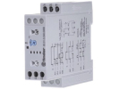
Analog Time Relays
Analog time setting is suitable where the operator needs to read the knob position directly and adjust the delay. Before choosing, however, determine the permissible deviation of the process: an approximate ventilation run-on has different requirements from a precisely linked technological step. A finely printed scale alone does not determine the accuracy of the actual switching.
This category includes, among others, EMAS RZ3A1A30S2, RZ1A2C03M-5, RELPOL RPC-1MA-UNI and FINDER 83.01.0.240.0000. These are different designs. Do not transfer the function, power supply or mounting accessories from one listed code to another.
Decision: range and repeatability
Start with the required time and the limits the process will still accept. The selected range should allow a reasonably readable setting; a scale that is too wide can make fine correction of a short delay difficult. Record the range and the knob position in the settings record. A photo of the pointer alone without marking seconds, minutes or hours is usually insufficient for later replacement.
FINDER catalogue, 83 series for type 83.01 separately specifies repeatability and setting accuracy relative to the full scale. These quantities are not interchangeable: similar results of repeated measurements do not yet confirm agreement with the value read on the scale.
Principle: what starts the timing
For 83.01, the same catalogue distinguishes between functions triggered by the power supply and functions with a control signal. With on-delay AI, the contact switches only after the time has elapsed; with interval DI, it switches immediately and returns after the time. For service, the timing diagram is therefore just as important as the set number.
The analog knob describes the way the time is entered, not an analog current output. If you need numeric entry and reading, compare Digital Time Relays. When deciding, also write down the requirement for a repeated command while running; without it, the comparison of two modes may remain incomplete.
Mounting and commissioning
Check access to the setting elements after the control cabinet is closed and that their labels can be read. For the socket version, include the socket and wiring in the space check. For type 83.01, the manufacturer requires the time function to be set without power. Do not convert this instruction into a universal procedure for any device; determine further actions according to its own manual.
During acceptance, measure the delay from the actual triggering event, not from pressing a remote button without verifying the signal path. Record which contact you are monitoring and at what power supply the test was carried out. After replacement, return to the same conditions so that the results can be compared.
Diagnostics of a different delay
First verify the unit and range, then the selected function, the triggering event and the reset conditions. Only then adjust the position of the knob. Different measurement starting points can create an apparent device error. Several repetitions with the same command help distinguish a permanent offset from irregular behaviour.
Author's model example: full-scale error
Consider a purely model error limit of ±2 % of the full scale of 40 seconds. This represents ±0.8 seconds, i.e. a relative ±8 % at a setting of 10 seconds. The value is not ±2 % of the ten seconds set. This is an author's calculation, not a parameter of any product offered here or a FINDER accuracy calculation.
FAQ
Can the exact switching moment be determined from the scale?
For the required tolerance, use the specification and a measurement. During the test, separate the measured time from the subsequent response of the controlled device.
Can a timer replace counting pieces?
Only if the requirement really depends on time. A variable flow of material requires verification of events; this is covered by the category Digital Counters.