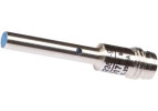
Extended-range inductive sensors offer a longer switching distance with the same housing diameter. They are suitable where the sensor cannot be placed close to the target. Choose by range, flush or non-flush mounting and the influence of surrounding metal.
IBR4017H from IPF is an extended-range inductive sensor. Ø4 mm, Sn 2.5 mm, 10–30 V DC, PNP, NO, connector M8, 3 pins.
Su richiesta
159,65 €
IVA esclusa · 193,18 € IVA inclusa
I prezzi includono il contributo di riciclaggio.
Long-range inductive sensors
A long-range inductive sensor offers an increased sensing distance for a given type of design. A larger gap can make mounting easier and reduce the risk of contact with a moving part. The benefit depends on the actual target, the free space around the head and the assured operating conditions.
LANBAO LR18XC-Y. Source: LANBAO, manufacturer. Original product image from the manufacturer. Check dimensions and connection according to the order code.
Rated range is not a mounting margin
The Sn value is used to compare sensors under defined conditions. For designing reliable detection, use the assured switching distance Sa and the rules specified by the manufacturer. The actual part may be smaller, thinner or made of a different metal than the reference target; the achievable working gap may change as a result.
Design value
Question for the designer
Largest gap
Does the hardest-to-detect part switch even with play, vibration and temperature changes?
Smallest gap
Is there a margin against contact during overtravel or deflection of the mechanism?
Surrounding metal
Will the head detect the bracket, an adjacent part or a metal background?
Direction of passage
Is the effective area of the target in the active zone long enough?
Mounting design
Do the embedding and free space match the exact installation drawing?
A larger field needs space
With a longer range, the influence of surrounding metal parts can become more pronounced. Do not adopt the bracket and spacing of the original model without checking. The designations flush, quasi-flush and non-flush mean different mounting conditions; the permissible embedding is defined by the specific drawing.
For the pictured LR18XC-Y series, LANBAO lists variants with a range of 12 and 20 mm with different mounting designs. Do not choose based on the higher number alone. Check the full variant code, its free space, electrical wiring and the available working gap.
Illustrative tolerance example: the nominal mechanical gap is 6 mm, the part position spread is ±1 mm and bracket movement can add another 1 mm. So verify reliable switching at 8 mm and a safe clearance at 4 mm. The calculation describes the geometry, not the usable range of a specific model.
Machine speed and pulse length
A long range alone does not guarantee that a short passage is captured. The switching frequency, sensor response and PLC processing are important. The indicator may signal a passage even though the input filter suppresses the short pulse. Compare the signal duration with the requirements of the whole control path.
As a guide, the passage time can be calculated as t = L / v. If the effective detection path is 10 mm and the speed is 1 m/s, the result is 10 ms. The actual length of the active path depends on the target and the sensor field, so confirm this estimate by measuring at working speed.
Selection and verification procedure
Write down the material, dimensions and direction of movement of the target.
Determine the extreme mechanical gaps and the position of surrounding metal.
Choose a mounting design with a suitable Sa, supply and output.
Test several real parts at the largest gap and the highest speed.
Check the states with no target, with a metal background and with usual operating contamination.
If a standard cylindrical model cannot handle the required clearance, also compare a suitable rectangular version. A larger active face can help, but the requirements for the target and the surrounding space must be re-evaluated.
FAQ
Can I replace a standard sensor with a longer-range model without modifications?
Only after checking the mounting conditions, space and electrical parameters. A longer range may cause detection of surrounding metal that did not affect the original model.
Will the long range be the same for aluminium and steel?
Only if the manufacturer declares it for the given metals and conditions, for example with the corresponding Factor 1. series
Why does the sensor stay switched on even without a product?
Check the metal bracket, background, adjacent components and deposits. A common cause is failure to keep the free space around the active part.
For a specific selection, prepare the material and dimensions of the target, the working gap, the environmental conditions and the required electrical connection. An overview can be found in the categories Special sensors and Inductive sensors.
Technical documents:LANBAO: LANBAO LR18XC-Y. This guide helps with selection; binding parameters, wiring and mounting are defined by the documentation of the ordered model.
Cookie su questo sito
I cookie tecnici servono per il funzionamento del carrello e dell'ordine — sono sempre utilizzati. I cookie analitici ci mostrano quali pagine le persone cercano e dove si perdono, e ci aiutano a migliorare il negozio. Li utilizziamo solo se ce lo consenti. Maggiori informazioni nella informativa sul trattamento dei dati.
Impostazioni cookie
Scegli quali cookie possiamo utilizzare. Puoi modificare la scelta in qualsiasi momento.
Cookie tecnici
Sempre attivi
Conservano il contenuto del carrello, l'accesso e la lingua scelta e proteggono i moduli dagli abusi. Senza di essi non è possibile completare l'ordine, per questo sono utilizzati anche senza consenso.
Cookie analitici
Google Analytics ci mostra in forma aggregata il traffico e il comportamento sul sito. Così capiamo quali pagine non funzionano per gli utenti. In base a questi dati non identifichiamo nessuno.