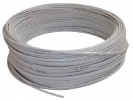
Bulk cables for sensor connection
A bulk cable is a line whose ends and connection method must be specified in the requirements. For sensor cabling, distinguish between supply, signal wires and any shielding. The suitability of the jacket, movement and environment is confirmed for the specific cable design.
Selection data: bulk cables
| Step |
What to document |
| Identification |
number of cores, cross-section and termination |
| Operating requirements |
movement and environment |
| Acceptance |
signal at the downstream input |
A bulk cable lets you adapt the line length to a specific machine and choose your own termination. The category includes, for example, the designations 2-57-405, 2.57.852-521, 2-57-852-434-4 and SUPER-Li-PUR in variants 3x0.25mm2 and 3x0.34mm2. These designations are not mutual substitutes. For ordering, prepare a list of the circuits to be carried, the route length and the requirements of the connecting terminals or connectors.
Decision: number of cores and cross-section answer different questions
The number of cores follows from the wiring diagram: count supply, signals and any other functions separately. Then assess the cross-section according to load, length and installation conditions. Even a cable with enough cores may not be suitable for the chosen terminal. For the termination, therefore, check the permissible conductor cross-section and the outer diameter of the whole cable; these are two different quantities.
The jacket material is only part of the specification. State whether the cable will remain fixed, be repositioned occasionally, or undergo repeated movement. DDA for its own PUR-FLEX series for example separates the data for fixed installation and movement. This series is not identical to the SUPER-Li-PUR offered: its temperatures and radii cannot be used as substitute parameters for another cable.
Principle: feed cable resistance and space for bending
A voltage drop occurs across the resistance of the supply conductors when current flows. For a simple two-wire supply section, include both the outward and return paths. If the length of one path is l, the resistance is approximately R = 2 × l × ρ / S. The drop is then ΔU = I × R. This simplified model does not include contacts, heating or varying load.
For mechanical design, use the radius specified for the specific operation. Explanation from the manufacturer igus shows the relationship of the radius to the outer diameter of the cable and points out the importance of the datasheet data. An arbitrarily chosen multiple of the diameter is not proof that the cable will withstand a given moving application. Therefore also add the actual route geometry to the requirements.
Mounting: termination starts with documentation
Before cutting, label both ends and create a wiring list from conductor to terminal. Use the core colour as an identifier, not as the only proof of its function. Determine the stripping method, treatment of the stranded end and tightening according to the instructions of the terminal or field-wireable connector. Check that sufficient length remains for the planned termination and that the cable fixing does not interfere with the bending point.
Author's model example, not a product parameter
Consider a copper feed cable 20 m long in one direction, cross-section 0.5 mm², current 0.1 A and a simplified resistivity of 0,0175 Ω·mm²/m. The resistance of the conductor pair is 1.4 Ω and the drop is 0.14 V. With an ideal 24 V source, 23.86 V would remain at the end. This is only an illustrative calculation; it does not verify the permissible current, actual resistance or suitability of a specific product.
Diagnostics: compare the line and the powered assembly
After assembling a separate cable, check the continuity of the conductors according to the list. For an operating problem, then compare the voltage at the beginning and end of the supply section under the same load condition. Record the measurement conditions so that a no-load state is not compared with the moment of switching. For an intermittent fault, also check points of repeated movement and transitions between fixed and free installation.
FAQ
Does PUR automatically mean a drag-chain cable?
For the decision, request the specification of the particular design and the movement conditions. The material abbreviation alone is not enough.
When does a ready-made cable make sense?
If the required length and interface are matched by cable with connector, there is no need to assemble this termination yourself. It is still necessary to check the whole route and wiring.