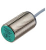
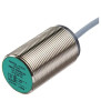
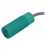
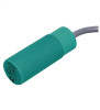
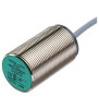
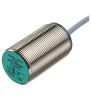
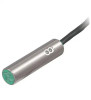
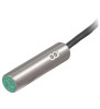
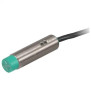
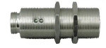
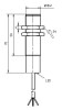
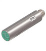
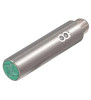
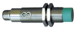
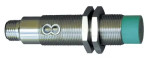
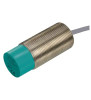
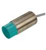
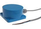
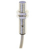
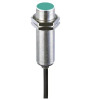
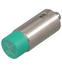
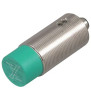
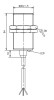
A cylindrical inductive sensor detects a metal object without contact and passes a switching signal to the control system. The threaded housing lets you set the working gap with nuts; however, a matching thread alone is not enough to choose a replacement.
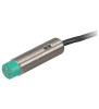
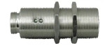
LANBAO product image, series LR12E. Source: manufacturer. Check the exact dimensions and connection in the documentation of the model.
How the switching signal is generated
A coil in the sensing face generates an alternating electromagnetic field. A metal target in the field induces eddy currents, which change the energy balance of the oscillator. The electronics evaluate this change and switch the output. A gap remains between the target and the face: the sensor must not be used as a mechanical stop.
The result depends on the material, size and position of the target. A small screw or a thin edge may require a smaller working gap than a large steel surface. For aluminium or stainless steel, do not use the range specified for a standard steel target without checking the correction factor of the specific model.
Choose the housing size together with the mounting space
Version
When it makes sense
What to check
M4 and M5
Small fixtures and confined spaces
Body length, fixing and strain relief of the thin cable.
M8
Compact mechanisms and position monitoring
Connector dimensions and space for the connection cable.
M12 and M18
Standard machine assemblies
The required gap, the mounting type (flush/non-flush) and access to the nuts.
M30
Larger mounting locations
Whether a larger body really provides the required range and target size.
The designation M12 describes the housing thread, not automatically the connector M12. Also check the thread pitch, overall length and the space needed to replace the sensor without removing surrounding parts.
Flush mounting and working distance
Flush sensor is designed to be mounted with its face level with the surrounding metal according to the installation drawing. Non-flush sensor needs free space around the active part. Embedding an unsuitable model in a metal bracket can cause permanent switching or reduce the usable gap.
Parameter
Meaning for design
Sn – rated operating distance
Reference value for a defined target and conditions; it does not replace verification in the application.
Sa – assured operating distance
Value for designing reliable switching within the limits specified by the manufacturer.
Hysteresis
Difference in position between switching on and off; prevents the output from chattering around the threshold.
Repeatability
Spread of repeated switching points under defined conditions; it is not the absolute accuracy of position measurement.
PNP, NPN and NO/NC logic
In a standard three-wire DC version, a PNP output supplies a positive potential when active, while an NPN output pulls it to 0 V. The type must match the PLC input. NO means an output activated by the presence of the target; NC uses the opposite logic. Take wire colours and pin numbers from the wiring diagram of the specific order code.
The LED on the sensor confirms the local state, not correct signal processing in the PLC. During commissioning, check the supply, output voltage, input indicator and the input value in the program at the same time.
Example: counting metal parts
A conveyor moves at 0.6 m/s and the part pitch is 60 mm. The passing frequency is f = v / p = 0.6 / 0.06 = 10 Hz. But that alone is not enough: with an effective detection length of 12 mm, the pulse lasts approximately t = 0.012 / 0.6 = 20 ms. The input filter and the PLC program must be able to capture such a pulse. Verify the length of the actual detection zone by measuring on a real part.
Check before ordering
Size and material of the target, its minimum and maximum distance.
Flush/non-flush mounting, available space and the manufacturer's tightening torque.
Supply, PNP/NPN, NO/NC, number of wires and pinout.
Speed of the process, input filtering and how the PLC reads the signal.
Temperature, degree of protection, chemical influences and cable suitability for movement.
Frequently asked questions from practice
Can I replace a M12 sensor with any other M12?
Also compare the length, mounting, range for the actual metal, electrical output and connector wiring. The same thread only ensures part of the mechanical compatibility.
Why does the sensor react to steel, but to aluminium only at close range?
Different metals may have a different correction factor. If materials alternate, consider a Factor 1 version and check its properties for the targets in question.
Can a reliable gap be determined from Sn alone?
The design must include the tolerances of the bracket and target, temperature and a margin against impact. Use the manufacturer's data and verify the worst operating condition.
Technical documents:ifm: mounting cylindrical and rectangular sensors. This guide describes the selection procedure; binding parameters and wiring are defined by the documentation of the ordered model.
Cookies on this website
We need technical cookies for the cart and checkout to work — these are always used. Analytics cookies show us which pages people look for and where they get lost, and help us improve the shop. We only use them if you allow it. More in the data processing policy.
Cookie settings
Choose which cookies we may use. You can change your choice at any time.
Technical cookies
Always active
They keep the cart contents, your login and selected language, and protect forms from abuse. An order cannot be completed without them, so they are used even without consent.
Analytics cookies
Google Analytics shows us traffic and behaviour on the website in aggregated form. This tells us which pages are not working for people. We do not identify anyone from this data.