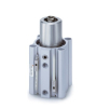
Pneumatic Clamps
A pneumatic rotary clamp allows the clamping arm to be swung out of the loading area and then pressed into the fixture. This category offers SMC MKB versions with right-hand and left-hand rotation. Selection starts with the arrangement of the support points and the required arm path; the cylinder diameter alone is not enough to assess the whole assembly.
Rotation and the actual clamping are two phases
According to the SMC MK catalogue clamping is carried out in the linear part of the stroke, not during rotation. The standard series requires vertical mounting and a clamping surface perpendicular to the cylinder axis. During clamping, the workpiece must not be moved by an external force in a way that subjects the piston rod to torsion. The manufacturer sets limits on the arm length depending on pressure and also assesses the moment of inertia of the arm relative to the speed of movement. The clamping stroke designation is not the total travel including the rotary part.
For the designer, this means two separate checks are needed: whether the arm passes safely through the space and whether it carries the required load in the end position. Free space with the fixture open does not prove a sufficient reserve for the product at the upper tolerance limit.
What to include in the fixture specification
- Draw the arm path, the space for the operator's hands and the collision contour of the product.
- State the minimum and maximum height of the clamped part including spacers and tolerances.
- Separate the force needed for clamping from the forces of machining or another working operation.
- Describe the arm by its dimensions, weight and centre of gravity; an approximate photo is not enough.
- Define how to check that the part is loaded, that the working position is reached and that the cycle may start.
The fixture supports should form a clearly defined base. When the product changes, verify again where the clamping force actually acts and whether it causes bending. The machine user also needs access for cleaning the support surfaces; a trapped chip can change the position of the part even though the clamp completes its usual movement.
Author's model example: force and arm length
Consider a model clamping force of 100 N at a distance of 40 mm from the axis. The corresponding static bending moment is M = F·l = 100 × 0.04 = 4 N·m. Extending the arm to 80 mm while keeping the same clamping force means 8 N·m. The same force requirement therefore does not mean the same stress.
This is a general calculation, not the permitted load of a specific MKB. It does not include the dynamics of rotation, the arm mass or design limitations. In the project, compare the actual geometry and operating pressure with the documentation of the selected model; simply increasing the pressure is not a universal solution for an arm that is too long.
Mounting, testing and maintenance
Before the first working cycle, verify the correct direction of rotation according to the manufacturer's drawing and the actual mounting orientation. Check the entire movement for collisions and then repeat with the limit dimensions of the part. Carry out adjustments in the safe mode of the machine. Before dismantling, secure the part against release and safely depressurise the circuit.
If the product position changes, record the cleanliness of the supports, the part dimension, the clamping pressure and the position reached. Look for a link with a specific change instead of adjusting several parameters at once. For the air supply, see air preparation and for motion control pneumatic valves.
FAQ
Can an arbitrarily longer arm be used when replacing?
No. The length changes the bending moment and the mass distribution. A new arm is a design change that requires new verification.
Is the rotary clamp also intended for transferring a part?
Here we primarily deal with clamping into a fixed fixture. For handling grips, compare gripper heads and assess separately how the part is held during movement.